Treatment process of cutting fluid wastewater

A treatment process and cutting fluid technology, applied in the field of cutting fluid wastewater treatment process, can solve the problems of incomplete water treatment steps, high energy consumption, secondary pollution, etc., and achieve excellent COD removal rate and oil removal rate, energy consumption Low, high removal effect

Active Publication Date: 2021-01-08
伸荣(上海)水处理环保工程有限公司
View PDF6 Cites 1 Cited by
  • Summary
  • Abstract
  • Description
  • Claims
  • Application Information

AI Technical Summary

Problems solved by technology

[0006] The above existing technologies need to add more auxiliary agents to help treat the cutting fluid wastewater, which is easy to cause secondary pollution, and consumes a lot of energy, and the water treatment steps are not comprehensive, and cannot completely remove all kinds of pollutants in the cutting fluid wastewater.

Method used


Image

  • Treatment process of cutting fluid wastewater
  • Treatment process of cutting fluid wastewater

Examples


preparation example Construction

[0034] The P(AN-MA) copolymer is self-made, and the preparation method includes the following steps: (1) the water bath is heated up to 60°C, and distilled water is added to a four-necked flask, and N 2 protection; (2) Weigh the emulsifier OP-10 and SDS (CAS No.: 151-21-3) into the four-necked flask and stir evenly, and install the condenser to reflux; (3) Measure the predetermined amount of AN (CAS No.: 107-13-1) and MA (CAS No.: 96-33-3) were mixed evenly, and dodecyl mercaptan (CAS No.: 112-55-0) was added to the four-necked flask; (4) after 1 hour of reaction , add the ammonium persulfate initiator for the first time, and add the mixed solution of AN and MA dropwise into the four-necked flask, control the rate of dropping to 1 drop / s, and the reaction time is 2 to 3 hours; (5) wait for After the dropwise addition is completed, add the ammonium persulfate initiator for the second time, and continue to react for 1 to 2 hours; (6) after the reaction is completed, take out the...

Embodiment 1

[0050] Embodiment 1 provides a cutting fluid wastewater treatment process, including the following steps: 1) Collect the cutting fluid wastewater into a physical sedimentation tank to remove large-sized particles and impurities; (2) evenly flow the wastewater through the electrocatalytic The Phaidon reactor is used for processing, the catalytic voltage is 25V, and the current density is 20mA / cm 2 , the amount of hydrogen peroxide added is 8g / h / L; (3) the treated waste water is passed into the settling tank, and sodium hydroxide is added to adjust the pH to 7.6, and 0.2wt% demulsifier of waste water weight is added to carry out demulsification (demulsifier is composed of cation Polyacrylamide, made by mixing epichlorohydrin-dimethyldiallylammonium chloride polymer and polyoxypropylene polyoxyethylene polyoxypropylene triblock polyether compound, the weight ratio is 1:3:1), After the demulsification is completed, the wastewater passes through the HP (AN-MA) ultrafiltration membr...

Embodiment 2

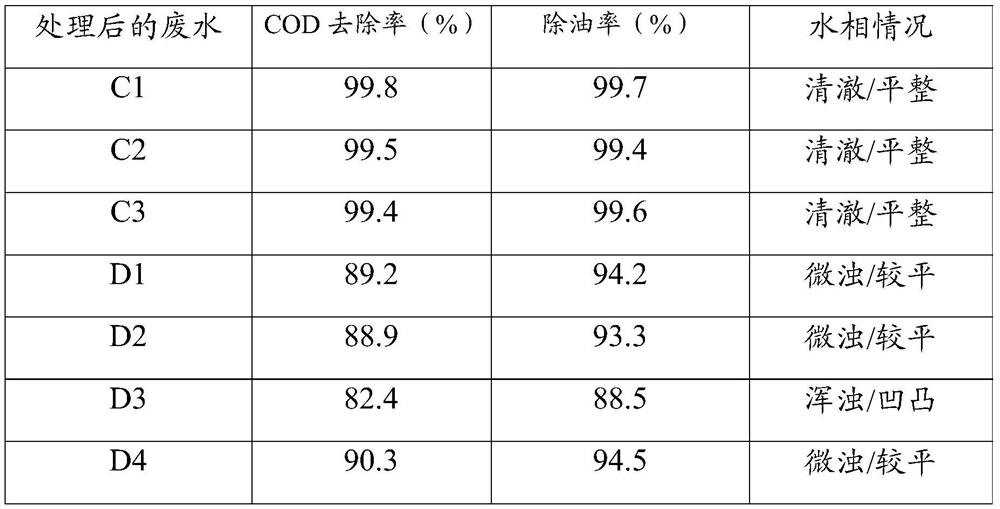
[0059] The specific implementation mode of this embodiment is the same as that of Example 1, the difference being: in the demulsifier, cationic polyacrylamide, epichlorohydrin-dimethyl diallyl ammonium chloride polymer and polyoxypropylene polyoxyethylene polyoxygen The weight ratio of the propylene triblock polyether compound is 1:2:1. The wastewater treated in this example is denoted as C2.


PUM

PropertyMeasurementUnit
concentrationaaaaaaaaaa

Abstract

The invention discloses a cutting fluid treatment process, which mainly comprises the following steps: adding sodium hydroxide to adjust the pH value to 7.6-8.5, adding a demulsifier to carry out demulsification, and carrying out oil-water separation ultrafiltration membrane separation on the wastewater after the demulsification is completed; adding the supernatant into a photocatalysis tank, andcarrying out photocatalytic membrane dynamic catalytic treatment to obtain a treatment solution; and adding the salt scale corrosion inhibitor into the treatment solution, and conveying to a concentration device for cyclic distillation to remove the salt solution to obtain a distillate. By limiting the molar ratio of the preparation raw materials, limiting the weight ratio of the compound demulsifier and functionally modifying TiO2, the cutting fluid treatment process with an excellent decontamination effect is researched, has extremely high COD removal rate and oil removal rate on cutting fluid wastewater, is suitable for being popularized and used as a cutting fluid treatment process in the field of water treatment, and has a wide development prospect.

Description

technical field [0001] The invention relates to the field of water treatment technology, in particular to a treatment technology for cutting fluid wastewater. Background technique [0002] Oily emulsified wastewater is a kind of wastewater that is difficult to treat, and it exists in large quantities in large iron and steel enterprises and mechanical processing industries. In the mechanical processing industry, in order to reduce friction, reduce thermal effects, prolong tool life, improve processing quality and production efficiency in metal cutting, grinding, drilling, wire drawing, and calendering, a large number of emulsified cutting fluids are used. During the cleaning of metal parts and equipment in many industrial sectors, a large amount of wastewater is generated, which contains oil, emulsion and cutting impurities washed from the parts. Oil-water emulsion composed of vegetable oil, emulsifier and water. Because the waste liquid contains a large amount of organic m...

Claims


Application Information

Patent Timeline
Patent Type & Authority Applications(China)
IPC IPC(8): C02F9/14C02F101/30
CPCC02F9/00C02F1/4672C02F1/725C02F1/66C02F1/444C02F1/40C02F5/08C02F1/048C02F1/50C02F3/34C02F2001/007C02F2305/10C02F2101/30C02F2209/08
Inventor 张峰张杰史红玉李春燕刘蕾蕾张翔
Owner 伸荣(上海)水处理环保工程有限公司
Why Eureka
Try Eureka