
Copper-based low-temperature shift catalyst and preparation method thereof

A shift catalyst, low temperature technology, applied in the field of copper-based low temperature shift catalyst and preparation, can solve the problems of lower specific surface, unstable catalyst structure, easy loss of alkali metal, etc., and achieve the effect of stable performance

Pending Publication Date: 2021-01-12
SINOPEC NANJING RES INST OF CHEM IND CO LTD +1
View PDF9 Cites 2 Cited by
  • Summary
  • Abstract
  • Description
  • Claims
  • Application Information

AI Technical Summary

Problems solved by technology

However, there are two disadvantages: first, the alkali metal is easy to lose under the conditions of high temperature, high pressure, and high steam-gas ratio, the activity of the catalyst declines seriously, and the phase change of the carrier causes the structure to be unstable
On the other hand, under the conditions of high pressure and low temperature, the hydration phase transition of the carrier inevitably occurs, which leads to the instability of the catalyst structure, a large decrease in the specific surface area, and irreversible deactivation of the catalyst.

Method used


Image

  • Copper-based low-temperature shift catalyst and preparation method thereof

Examples

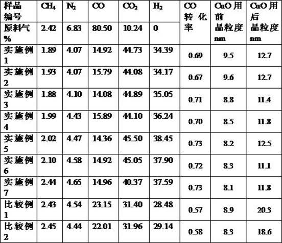

Embodiment 1

[0029] Will Cu 2+ Cu(NO 3 ) 2 Solution 2L, Zn 2+ Zn(NO 3 ) 2 Solution 0.6L, configured in a neutralization tank as a mixed solution 1, heated to 70°C under stirring;

[0030] Dilute 100g of JA-25 silica sol to 400mL to form solution 2;

[0031] Add solution 2 into solution 1 and stir well to form solution 3;

[0032] Prepare Na in the alkali tank 2 CO 3 Alkaline solution, 0.1Kg of soda ash per liter of water is made into precipitant solution 4;

[0033] Solution 4 was added to solution 3, and the end point pH value was 7.8 to form slurry 1;

[0034] Weigh 50g of pseudo-boehmite, add 50g of magnesium oxide powder into slurry 1, and beat for 20min.

[0035] After the slurry I after beating is filtered, washed and dried, K is added 2 CO 3 10 g was ground and granulated, calcined at 450° C., added graphite and pressed into pellets to obtain the catalyst.

Embodiment 2

[0037] Will Cu 2+ Cu(NO 3 ) 2 Solution 4L, Zn 2+ Zn(NO 3 ) 2 Solution 1.6L, configured in a neutralization tank as a mixed solution 1, heated to 70°C under stirring;

[0038] Dilute 100g of JA-25 silica sol to 400mL to form solution 2;

[0039] Add solution 2 into solution 1 and stir well to form solution 3;

[0040] Prepare Na in the alkali tank 2 CO 3 Alkaline solution, 0.1Kg of soda ash per liter of water is made into precipitant solution 4;

[0041] Solution 4 was added to solution 3, and the end point pH value was 7.8 to form slurry 1;

[0042] Weigh 25g of magnesia-alumina spinel and add it into the slurry 1, beat for 20min.

[0043] After the beating slurry 1 was filtered, washed and dried, CaCO was added 3 10g, K 2 CO 3 10 g was ground and granulated, calcined at 500° C., added graphite and pressed into pellets to obtain the catalyst.

Embodiment 3

[0045] Will Cu 2+ Cu(NO 3 ) 2 Solution 2L, Zn 2+ Zn(NO 3 ) 2 Solution 0.5L, configured in a neutralization barrel to form a mixed solution 1, heated to 60°C under stirring;

[0046] Dilute 150g of JA-25 silica sol to 400mL to form solution 2;

[0047] Add solution 2 into solution 1 and stir well to form solution 3;

[0048] Prepare Na in the alkali tank 2 CO 3 Alkaline solution, 0.1Kg of soda ash per liter of water is made into precipitant solution 4;

[0049]Solution 4 was added to solution 3, and the end point pH value was 7.2 to form slurry 1;

[0050] Weigh 200g of pseudo-boehmite and 70g of magnesium oxide powder into the slurry 1, beat for 20min.

[0051] After the beating slurry 1 was filtered, washed and dried, CaCO was added 3 10 g was ground and granulated, calcined at 420° C., and graphite was added to form a tablet to obtain the catalyst.


PUM


Abstract

The invention relates to a copper-based low-temperature shift catalyst and a preparation method thereof, and aims to solve the problem of fusion growth of copper microcrystals of the existing copper-based catalyst under high load. By changing the formula and the preparation method of the copper-based low-temperature shift catalyst, the CO conversion depth advantage of the copper-based low-temperature shift catalyst is exerted, the dispersity of copper crystallites in the catalyst is improved, the copper crystallites are prevented from melting and growing up under high load, and the copper-based low-temperature shift catalyst has higher conversion rate, structural stability and service life under high-carbon low-temperature shift reaction. The catalyst disclosed by the invention mainly comprises CuO, ZnO, Al2O3, SiO2, alkali metal and alkaline-earth metal, is suitable for an atmosphere with CO content of 50% or more in feed gas, and is also suitable for deep conversion of CO in an atmosphere with CO content of 10% or less in the feed gas.

Description

technical field [0001] The invention belongs to the technical field of catalysts, and in particular relates to a copper-based low-temperature shift catalyst and a preparation method. Background technique [0002] The CO shift reaction is an exothermic reaction, and lowering the temperature of the shift reaction is beneficial to the reaction to obtain a lower CO equilibrium concentration. In the synthetic ammonia and hydrogen production industries that use natural gas and coke oven gas as raw materials, hydrogen production through synthetic gas is generally carried out in two stages: the high-temperature shift stage with a reaction temperature of 350°C to 400°C, and the reaction temperature at about 180°C ~220°C low temperature shift stage. The high-temperature shift stage reacts most of the carbon monoxide to improve production efficiency and energy recovery efficiency, and the low-temperature shift stage is conducive to the deep conversion of carbon monoxide. [0003] The...

Claims


Application Information

Patent Timeline
IPC IPC(8): B01J23/06B01J35/10C01B3/16
CPCB01J23/06C01B3/16C01B2203/0283C01B2203/1076B01J35/60Y02P20/52
Inventor 吴结华袁浩然李兴田李婷婷
Owner SINOPEC NANJING RES INST OF CHEM IND CO LTD
Learn More