Slitting and winding device for filter paper production and method
A winding device and filter technology, applied in metal processing and other directions, can solve the problems of reduced cutting quality of filter paper cutting surface, unfavorable filter paper processing quality, lack of pre-compression device and other problems, so as to improve the quality of slitting and winding, prevent filter paper The appearance of wrinkles and the effect of easy slitting work
- Summary
- Abstract
- Description
- Claims
- Application Information
AI Technical Summary
Problems solved by technology
Method used
Image

Examples
Embodiment 1
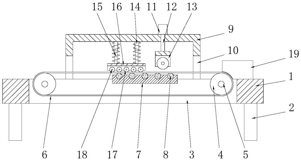
[0031] See figure 1, a cutting and winding device for filter paper production, comprising a workbench 1, the bottom of the workbench 1 is symmetrically provided with legs 2, and the workbench 1 is provided with a transfer chamber 3, and the transfer chamber 3 Through connecting the upper and lower end surfaces of the workbench 1, the inner cavity of the transmission cavity 3 is symmetrically provided with transmission rollers 4 on the left and right sides, and the transmission rollers 4 are connected to the transmission cavity 3 through the transmission shaft 5. The transmission chain 6 is connected, and one end of the transmission shaft 5 runs through the side wall of the transmission cavity 3 and is connected to the external motor (not shown in the figure) in rotation. The top side of the workbench 1 is provided with the transmission chain 6 The cooperating winding box 19 drives the transmission roller 4 to rotate through the external motor and the transmission shaft 5, and ...
Embodiment 2
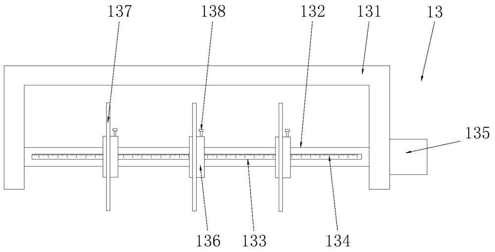
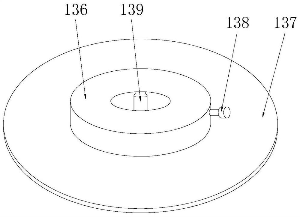
[0036] See Figure 2-3 , the difference from Embodiment 1 is that the distance-dividing cutter assembly 13 includes a tool holder 131, which is a U-shaped structure, and the inner cavity of the tool holder 131 is provided with a cutter shaft 132, and the cutter shaft 132 One end runs through the knife rest 131 and is connected to the cutting motor 135 in rotation. The knife shaft 132 is rotatably connected to the knife rest 131. The front of the knife shaft 132 is provided with a chute 133, and the inner cavity wall of the chute 133 is provided with a scale line 134, the outer sleeve of the cutter shaft 132 is provided with a number of cutter sleeves 136 matched with the chute 133, the cutter sleeve 136 is slidingly connected with the cutter shaft 132, and the inner cavity of the cutter sleeve 136 is provided with a sliding The clip 139 matched with the groove 133 is integrally formed between the cutter cover 136 and the clip 139. The outer circular surface of the cutter cover...
Embodiment 3
[0038] See Figure 4 , the difference from Embodiment 1 is: the legs 2 include a leg frame 21, the leg frame 21 is a rectangular ring frame structure, the leg frame 21 is fixedly connected to the bottom end of the workbench 1, the bottom wall of the leg frame 21 Left and right symmetry is provided with walking hole 22, and the inner cavity of described walking hole 22 is provided with frame 23, and the top of described frame 23 is fixedly connected on the inner cavity top wall of leg frame 21, and frame 23 is U-shaped structure, the top wall of the inner chamber of the frame 23 is fixedly connected to the hydraulic cylinder 24, and the bottom end of the hydraulic rod 25 on the hydraulic cylinder 24 is fixedly connected to the lifting seat 26 matched with the frame 23, and the lifting seat 26 is on the machine. The inner cavity of the frame 23 can slide freely, and the bottom end of the lifting seat 26 is fixedly connected with the traveling wheels 27, and the hydraulic rod 25 ...
PUM
 Abstract
Description
Claims
Application Information
 - R&D
- Intellectual Property
- Life Sciences
- Materials
- Tech Scout
- Unparalleled Data Quality
- Higher Quality Content
- 60% Fewer Hallucinations
Browse by: Latest US Patents, China's latest patents, Technical Efficacy Thesaurus, Application Domain, Technology Topic, Popular Technical Reports.
© 2025 PatSnap. All rights reserved.Legal|Privacy policy|Modern Slavery Act Transparency Statement|Sitemap|About US| Contact US: help@patsnap.com