
Laser radar, and two-dimensional scanning method of laser radar

A laser radar and laser beam technology, applied in the field of two-dimensional scanning, can solve the problems of large volume, low resolution, and increased difficulty, and achieve the effects of simple device structure, improved resolution, and increased density

Pending Publication Date: 2021-02-05
HANGZHOU GUANGPO INTELLIGENT TECH CO LTD
View PDF0 Cites 0 Cited by
  • Summary
  • Abstract
  • Description
  • Claims
  • Application Information

AI Technical Summary

Problems solved by technology

At present, relatively mature laser radars include mechanical scanning radar and non-scanning radar; currently scanning laser radar occupies a relatively large market share; from the existing technology, there are two types of scanning laser radar, one is mechanical scanning, through The motor drives the mirror to rotate, and uses the principle of geometric optics to realize the deflection of the beam, and scans out a three-dimensional point cloud image; this method of scanning can be counted as a point scanning method, but the disadvantage is that the resolution is relatively low, and it can only be resolved at a long distance. objects with a relatively large volume
[0003] The other is MEMS (Micro Electromechanical System, micro-electromechanical system) scanning, which realizes beam scanning through the rapid vibration of micro-mirrors; its system is relatively small, which can well overcome the shortcomings of large mechanical scanning systems; but MEMS can do a little When scanning, the speed is slow, the repeatability is poor, and there is also the problem of low resolution; when MEMS is used for line scanning, the resolution is improved, but limited by the caliber of the MEMS device, the difficulty of system design increases

Method used


Image

  • Laser radar, and two-dimensional scanning method of laser radar
  • Laser radar, and two-dimensional scanning method of laser radar

Examples


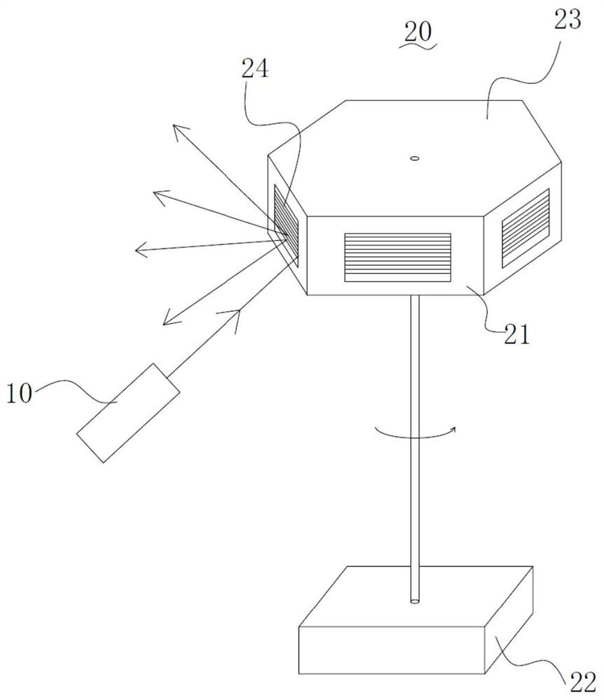
Embodiment Construction

[0027] The present invention will be described in detail below in conjunction with the specific embodiments shown in the accompanying drawings, but these embodiments do not limit the present invention, those of ordinary skill in the art make structural, method, or functional changes based on these embodiments All are included in the scope of protection of the present invention.

[0028] See figure 1 , figure 1 It is a structural schematic diagram of the laser radar of the present invention. As shown, the lidar includes a tunable laser 10 and a scanning device 20 . The tunable laser 10 is used to output a laser beam with continuously variable wavelength, and its working band can cover the spectral range from near ultraviolet to far infrared, and in the present invention, it is preferably light from visible light to infrared band. The tunable laser 10 usually has a fixed position relative to the scanning device 20 , and its own outgoing light angle is also relatively fixed, t...


PUM


Abstract

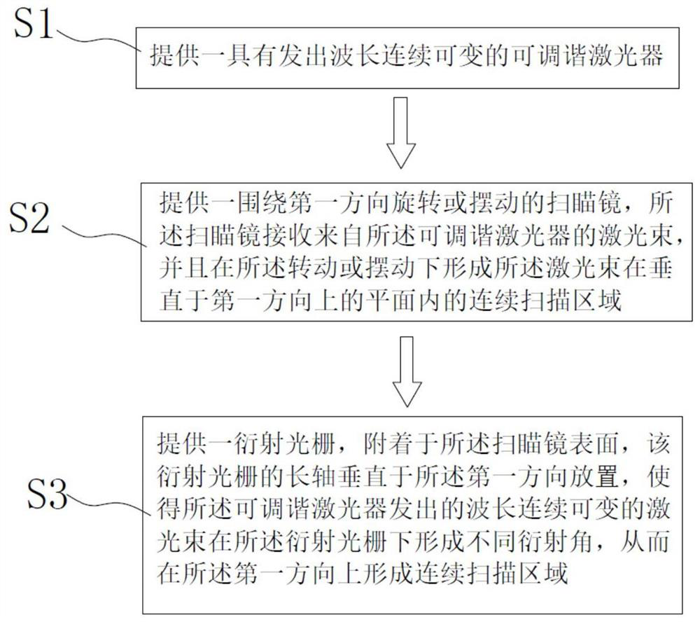
The invention discloses a laser radar and a two-dimensional scanning method of the laser radar. The laser radar comprises at least one tunable laser and a scanning device, and the tunable laser is used for outputting a laser beam with continuously variable wavelength; and the scanning device comprises at least one scanning mirror and a driving device, and a diffraction grating is arranged on the scanning mirror and can have different diffraction angles for light of different wave bands. Continuous scanning in the horizontal one-dimensional direction is achieved through vibration or rotation ofthe scanning mirror, laser beams with different emergent angles are obtained through grating diffraction by changing the wavelength output by the tunable laser, and scanning in the vertical two-dimensional direction is achieved. According to the invention, the density of the laser point cloud is increased, the resolution of the spatial orientation is improved, and the device is simple in structure and easy to realize.

Description

technical field [0001] The invention relates to the technical field of laser radar, in particular to a laser radar and a two-dimensional scanning method of the laser radar. Background technique [0002] Lidar is a device that uses laser beams to search and track targets and accurately measure the target's orientation, distance and speed. Compared with microwave radar, lidar has the advantages of high resolution, good concealment, good low-altitude detection performance, small size, and light weight. At present, relatively mature laser radars include mechanical scanning radar and non-scanning radar; currently scanning laser radar occupies a relatively large market share; from the existing technology, there are two types of scanning laser radar, one is mechanical scanning, through The motor drives the mirror to rotate, and uses the principle of geometric optics to realize the deflection of the beam, and scans out a three-dimensional point cloud image; this method of scanning ...

Claims


Application Information

Patent Timeline
IPC IPC(8): G01S17/02G01S17/06G01S7/481
CPCG01S17/02G01S17/06G01S7/4817
Inventor 黄锦熙俞佳晨巩少斌陈一帆白云峰
Owner HANGZHOU GUANGPO INTELLIGENT TECH CO LTD
Learn More