
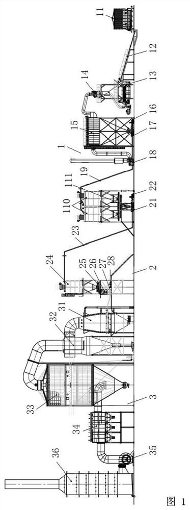
Ceramic raw material workshop dry-method micro-coal powder direct-injection combustion system

A technology of combustion system and ceramic raw materials, applied in combustion method, combustion equipment, combustion product treatment and other directions, can solve the problems of inability to meet production needs, incomplete combustion, serious environmental pollution, etc., and achieve significant social and economic benefits, The effect of improving utilization efficiency and avoiding environmental pollution

Inactive Publication Date: 2021-02-19
佛山市精科机械有限公司
View PDF0 Cites 0 Cited by
  • Summary
  • Abstract
  • Description
  • Claims
  • Application Information

AI Technical Summary

Problems solved by technology

[0003] In the traditional coal water slurry or chain grate furnace combustion system, due to the poor fluidity of the previous micro-coal, it is prone to clogging problems and serious environmental pollution, so it has been difficult to promote, and the entire system consumes a lot of energy and burns Incomplete, high emission and complex operation, while the production line has the disadvantages of high noise and many personnel interactions, resulting in low efficiency and unable to meet production needs

Method used


Image

  • Ceramic raw material workshop dry-method micro-coal powder direct-injection combustion system
  • Ceramic raw material workshop dry-method micro-coal powder direct-injection combustion system

Examples


Embodiment Construction

[0027] The following will clearly and completely describe the technical solutions in the embodiments of the present invention with reference to the accompanying drawings in the embodiments of the present invention. Obviously, the described embodiments are only some, not all, embodiments of the present invention. Based on the embodiments of the present invention, all other embodiments obtained by persons of ordinary skill in the art without making creative efforts belong to the protection scope of the present invention.

[0028] see Figure 1-2 , the present invention provides a technical solution: a dry-process micro-coal direct injection combustion system for a ceramic raw material workshop, including a micro-coal processing system 1, a micro-coal remote delivery system 2 and a micro-coal direct injection combustion system 3. In the processing system 1, the raw coal enters the air-swept continuous coal mill 13 through the feeding system equipment through the belt conveyor 12,...


PUM


Abstract

The invention relates to the technical field of ceramic raw material dry-method micro-coal combustion, and particularly relates to a ceramic raw material workshop dry-method micro-coal powder direct-injection combustion system. The ceramic raw material workshop dry-method micro-coal powder direct-injection combustion system comprises a micro-coal processing system, a micro-coal remote conveying system and a micro-coal direct-injection combustion system. In the micro-coal processing system, raw coal enters an air-swept continuous coal mill through a belt conveyor by means of feeding system equipment, the air-swept continuous coal mill grinds the raw coal into dry micro-coal powder with the fineness being 100-120 meshes by adopting a totally-closed powder making technology, the dry micro-coal powder is pumped out of the mill along with hot air and then enters a coal powder storage tank, and the dry micro-coal powder in the coal powder storage tank is conveyed into the micro-coal direct-injection combustion system through the remote conveying system and then conveyed into a raw material workshop combustion storage tank. According to the ceramic raw material workshop dry-method micro-coal powder direct-injection combustion system, the purposes of improving the micro-coal powder combustion efficiency and reducing pollution are achieved, and the utilization efficiency of coal combustion can be improved; and meanwhile, the whole combustion system is intelligently controlled in the whole process, operation is easy and convenient, heat supply is accurate, and thus the ceramic raw material workshop dry-method micro-coal powder direct-injection combustion system has remarkable social benefits and economic benefits.

Description

technical field [0001] The invention relates to the technical field of dry micro-coal combustion of ceramic raw materials, in particular to a direct injection combustion system of dry micro-coal powder in a ceramic raw material workshop. Background technique [0002] my country's ceramic industry is developing very rapidly. The ceramic spray tower combustion system is an important energy-consuming link in the ceramic production process. The research and engineering application of advanced ceramic spray tower combustion technology is of great significance to the development of the ceramic production industry. [0003] In the traditional coal water slurry or chain grate furnace combustion system, due to the poor fluidity of the previous micro-coal, it is prone to clogging problems and serious environmental pollution, so it has been difficult to promote, and the entire system consumes a lot of energy and burns Incomplete, high emission and complex operation, while the productio...

Claims


Application Information

Patent Timeline
Patent Type & Authority Applications(China)
IPC IPC(8): F24H3/00F23J15/02F23K1/00F23K3/00F23K3/02B02C21/00B02C23/04B02C23/20B01D1/14B01D1/18
CPCB01D1/14B01D1/18B02C21/00B02C23/04B02C23/20F23J15/02F23J15/025F23J15/027F23J2215/20F23J2217/101F23J2217/40F23K1/00F23K3/00F23K3/02F23K2201/10F23K2201/30F24H3/006
Inventor 刘涛
Owner 佛山市精科机械有限公司
Learn More