Bonding composition, bonding structure of electric conductor, and method for manufacturing same

A technology of bonding structure and composition, applied in conductive connection, conductive materials dispersed in non-conductive inorganic materials, circuits, etc., can solve the problems of inability to apply driving, low heat resistance of solder, etc.

Pending Publication Date: 2021-03-02
MITSUI MINING & SMELTING CO LTD
View PDF11 Cites 0 Cited by
  • Summary
  • Abstract
  • Description
  • Claims
  • Application Information

AI Technical Summary

Problems solved by technology

[0004] However, solder conventionally used as a bonding material has low heat resistance and cannot be used to drive WBGs at temperatures exceeding 175°C.

Method used


Image

  • Bonding composition, bonding structure of electric conductor, and method for manufacturing same
  • Bonding composition, bonding structure of electric conductor, and method for manufacturing same
  • Bonding composition, bonding structure of electric conductor, and method for manufacturing same

Examples


Embodiment 1

[0082] (1) Preparation of the composition for joining

[0083] As copper powder, D SEM50 Spherical copper powder of 0.16 μm. As a reducing agent, bis(2-hydroxyethyl)iminotris(hydroxymethyl)methane was used. The reducing agent is solid at 25°C, has a melting point of 104°C and a boiling point of over 300°C. As the liquid medium, ethylene glycol was used. The boiling point of this liquid medium was 197°C. These are mixed to obtain a pasty joining composition. The ratio of the reducing agent in the joining composition was 2.5 parts with respect to 100 parts of copper powder, and the ratio of the liquid medium was 22.5 parts with respect to 100 parts of copper powder. In addition, the shear rate of 10s -1 The viscosity of the joining composition at 25° C. was 25 Pa·s.

[0084] (2) Manufacture of joint structure

[0085] The bonding composition was applied by screen printing to the center of a 10 mm square copper plate (thickness 0.5 mm) to form a coating film. The coating...

Embodiment 2

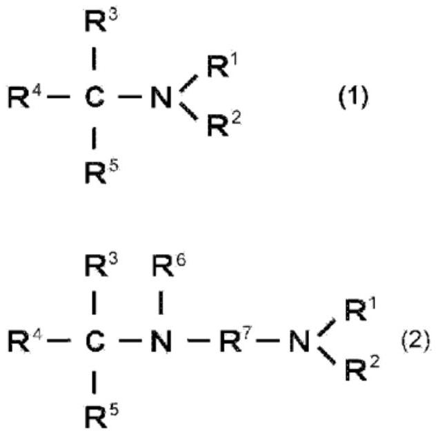
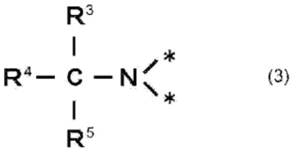
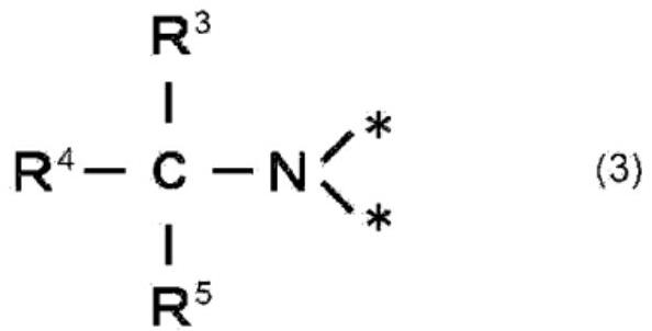
[0088] The ratio of the reducing agent in the joining composition to 100 parts of copper powder was set to 5.0 parts, and the ratio of the liquid medium to 100 parts of copper powder was set to 20.0 parts, in the same manner as in Example 1. It was operated to obtain a paste-like composition for joining. In addition, the shear rate of 10s -1 The viscosity of the joining composition at 25° C. was 42 Pa·s. Furthermore, a dried coating film was obtained under the same conditions as in Example 1. In addition, the content of the liquid medium in the dried coating film was confirmed to be 4% by mass or less. In addition, the bonded structure was produced under the same conditions as in Example 1. It was confirmed by mass analysis by TOF-SIMS that the structure represented by the above-mentioned structure (3) was formed at the copper junction.

Embodiment 3

[0098] Change the copper powder in the joining composition to D SEM50 0.14μm spherical copper powder with D 50 A mixture of flaky copper powders with a thickness of 4.9 μm and an aspect ratio of 13. The content ratio of the spherical copper powder and the flaky copper powder in the copper powder mixture was set to 70% by mass of the spherical copper powder: 30% by mass of the flaky copper powder. In addition, the ratio of the reducing agent was set to 2.5 parts with respect to 100 parts of copper powder. Furthermore, the liquid medium was changed to a mixture of polyethylene glycol 300 and hexylene glycol. The content ratio of each liquid medium with respect to 100 parts of copper powders was set as shown in Table 2. In addition, it carried out similarly to Example 1, and obtained the paste-form joining composition. Shear speed 10s -1 The viscosity of the joining composition at 25° C. was 34 Pa·s. Furthermore, a dried coating film was obtained under the same conditions a...


PUM

PropertyMeasurementUnit
viscosityaaaaaaaaaa
boiling pointaaaaaaaaaa

Abstract

This bonding composition comprises copper powder, a liquid medium, and a reducing agent, wherein the reducing agent has at least one amino group and a plurality of hydroxyl groups, the reducing agenthas a boiling point that is higher than the boiling point of the liquid medium, and the reducing agent has a melting point that is lower than or equal to the sintering temperature of the copper powder. The reducing agent is preferably bis(2-hydroxyethyl)iminotris(hydroxymethyl)methane. The bonding composition preferably has a viscosity at a shear velocity of 10/s and 25 DEG C of 10 to 200 Pa*s. The bonding composition preferably comprises, relative to 100 parts by mass of the copper powder, 0.1 to 10 parts by mass of the reducing agent and 10 to 40 parts by mass of the liquid medium.

Description

technical field [0001] This invention relates to the composition for joining used for joining two parts. Moreover, this invention relates to the manufacturing method of the junction structure of a conductor using this joining composition, and the junction structure of a conductor manufactured by this method. Background technique [0002] With the global trend of energy saving in recent years, semiconductor devices called power devices are widely used as power conversion and control devices such as inverters. Unlike integrated circuits such as memories and microprocessors, power devices generate a large amount of heat when driven because they are used to control high current. Therefore, in order to prevent the semiconductor element from being damaged by the heat, heat dissipation measures such as a cooling system are required for the semiconductor package. [0003] Incidentally, in order to greatly improve the energy utilization efficiency of devices, various semiconductor ...

Claims


Application Information

Patent Timeline
Patent Type & Authority Applications(China)
IPC IPC(8): B22F9/00B22F1/00B22F7/04H01B1/20H01R11/01H01R43/00B22F1/10B22F1/103B22F1/107B22F1/145
CPCB22F7/064H01B1/22B22F1/107H01L2224/8384H01L2224/95H01L2224/83203H01L24/83H01L2924/10272H01L2924/1033H01L24/29H01L2224/29294H01L2224/29347H01L2224/2939H01L2224/2732H01L2224/27312H01L2224/2731H01L2224/27848H01L2224/83075H01L24/32H01L24/27H01L24/95B22F1/10B22F1/145B22F1/103H01L2224/83H01L2924/00014H01L2924/00012B22F9/24B22F7/04H01B1/20H01R11/01H01R43/00
Inventor 穴井圭山内真一
Owner MITSUI MINING & SMELTING CO LTD
Why Eureka
Try Eureka