Dispersion confocal autorotation endoscopic detection method and device

A detection method and detection device technology, applied in the direction of measurement devices, optical devices, color/spectral characteristic measurement, etc., can solve the problems of limited measurement accuracy, low accuracy, and difficulty in miniaturization, and achieve high measurement accuracy and high rotation accuracy , the effect of small rotating mass

Pending Publication Date: 2021-03-05
绍兴钜光光电科技有限公司
View PDF0 Cites 3 Cited by
  • Summary
  • Abstract
  • Description
  • Claims
  • Application Information

AI Technical Summary

Problems solved by technology

[0004] Among the above measuring methods and measuring equipment, the inner diameter dial gauge method has low accuracy due to large positioning errors, and the measurement efficiency is low due to the need to contact the inner surface of hole parts, and cannot be realized due to the low lateral resolution of the probe. Detection of defects on the inner surface of parts; in addition, this method cannot realize the detection of special-shaped holes
The three-coordinate measurement method has high precision, but the measurement flexibility and measurement efficiency are low, and defect information cannot be obtained; the laser distance measurement method has a complex structure, large volume, and many movements, and the accuracy is difficult to guarantee. It is more suitable for large-sized hole parts. It is difficult to miniaturize and obtain information such as defects
The accuracy of the fringe projection method is limited by the quality of the projected sinusoidal fringes, but the projected fringes need to pass through the glass tube and there is a certain deformation. The existence of the above errors limits its measurement accuracy
The circular structured light method cannot obtain defect information with high resolution because the beam projected on the inner surface of the hole is not focused. In addition, this method is essentially an optical triangulation method, and its measurement accuracy is limited

Method used


Image

  • Dispersion confocal autorotation endoscopic detection method and device
  • Dispersion confocal autorotation endoscopic detection method and device
  • Dispersion confocal autorotation endoscopic detection method and device

Examples


Embodiment 1

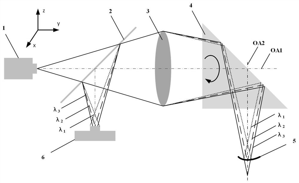
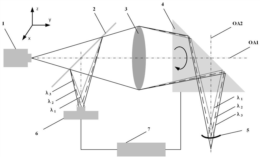
[0031] Such as Figure 4As shown, the fiber-optic dispersion confocal self-rotating endoscopic detection device used in this embodiment includes a multimode fiber-coupled broadband light source 101, a multimode fiber coupler 201, a fiber flange 8, a multimode fiber 9, and a dispersion objective lens 3 (including achromatic lens 301, concave lens 302, convex lens 303, convex lens 304, and convex lens 305), beam deflection mechanism 4 (including cylinder 401, bearing 402, prism 403), fiber optic spectrometer 601, and microprocessor 7. Among them, the multimode fiber-coupled broadband light source 101 is a broadband point light source by collimating and focusing the broadband light source to the multimode fiber, and using the multimode fiber port as the exit port; the multimode fiber coupler 201 is a passive optical fiber The device makes the light entering the coupler propagate along a fixed path to achieve light splitting; the dispersion objective lens 3 consists of an achromat...

Embodiment 2

[0037] Different from Embodiment 1, the displacement information analysis of the measurement beam direction in this embodiment comes from the focus position of the calibrated dispersion objective lens 3 in the measurement beam direction and the discrete spectral signal (including wavelength and intensity information) collected by the fiber optic spectrometer 601 The mapping relationship between the peak wavelengths. In the device of the present invention, components such as the dispersion objective lens 3, the multimode fiber-coupled broadband light source 101, the fiber optic spectrometer 601, the fiber flange 8 and the multimode fiber 9 have non-uniform spectral response characteristics, which often cause the actual displacement-wavelength relationship to deviate from the design The displacement-wavelength relationship (such as Figure 6 shown). In order to construct the actual mapping relationship between the focus of the dispersive objective lens 3 in the direction of the...

Embodiment 3

[0039] The difference from Embodiment 1 is that the broadband point light source in this embodiment is a common broadband point light source 102 collimated by the collimating mirror 103, then enters the focusing mirror 104 to focus, and is spatially filtered by the spatial filter 104 to obtain a broadband point source that meets the requirements of confocal detection. point light sources such as Figure 10 shown.


PUM

PropertyMeasurementUnit
wavelengthaaaaaaaaaa

Abstract

The invention belongs to the technical field of dispersion confocal displacement measurement, wherein the detection of the inner surface topography information of a hole sample can be rapidly achievedby using a self-rotating light beam deflection technology and combining a dispersion confocal displacement measurement technology. According to the method, a light beam deflection mechanism is used for deflecting a measurement light beam emitted by a dispersion objective lens by a certain angle and focusing the measurement light beam on the inner surface of a hole sample, a confocal spectrum detection system is used for spatially filtering the light beam reflected by the hole sample and detecting the spectral information of the light beam, the displacement information of the inner surface ofthe hole sample in the optical axis direction of the measurement light beam is obtained by processing the detected spectral information, and the optical axis of the measurement light beam rotates around the optical axis of the dispersion objective lens to be focused at different positions of the inner surface of the hole sample by rotating the light beam deflection mechanism, so that the displacement information of different positions of the inner surface of the hole sample in the optical axis direction of the measurement light beam is obtained. According to the invention, the light beam deflection technology and the dispersion confocal measurement technology are combined, so that the inner surface topography information of the hole sample can be directly measured, and a new idea is provided for detection of the inner surface size error, the shape error, the position error and the defect information of the hole sample.

Description

technical field [0001] The invention belongs to the technical field of dispersion confocal displacement measurement. The invention can be applied to the measurement of the inner surface topography of hole-like parts and the thickness measurement of hole-like transparent media, so as to realize the endoscopic detection of the inner surface of the hole-like parts. Background technique [0002] Hole parts such as bearings, cylinders, hydraulic cylinders and gun barrels are widely and important used in the automotive industry and defense industry. However, factors such as tool disturbance and vibration during the manufacturing process often make it difficult to guarantee the machining accuracy of hole parts, such as size errors, shape errors, and position errors that exceed tolerance requirements. In addition, hole parts are often used in shaft-hole fits, and usually face severe wear, vibration, and thermal environments. Therefore, cracks and other defects are prone to occur on ...

Claims


Application Information

Patent Timeline
Patent Type & Authority Applications(China)
IPC IPC(8): G01N21/90G01N21/25G01B11/00G01B11/02G01B11/25G01B11/06
CPCG01B11/00G01B11/02G01B11/06G01B11/25G01N21/25G01N21/255G01N21/90
Inventor 杨佳苗陈成沈阳刘林仙周纪冲邹高宇童强陈晋瑜
Owner 绍兴钜光光电科技有限公司
Why Eureka
Try Eureka