Transmission electron microscope sample rod system with ultrafast time-resolved spectrum capability and application
A technology of time-resolved spectroscopy and electron microscopy, which is applied in the fields of microscopy, optics, and analytical materials, and can solve problems such as direct correlation of material properties and single function
- Summary
- Abstract
- Description
- Claims
- Application Information
AI Technical Summary
Problems solved by technology
Method used
Image
Examples
Embodiment 1
[0047] This embodiment is used to illustrate the structure of the transmission electron microscope sample rod system of the present invention.
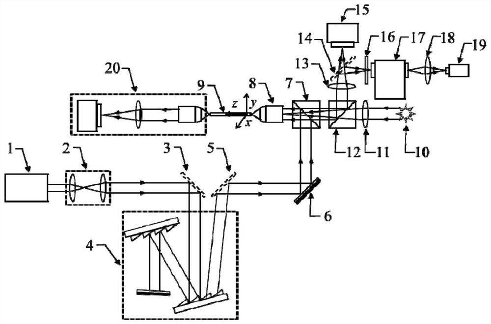
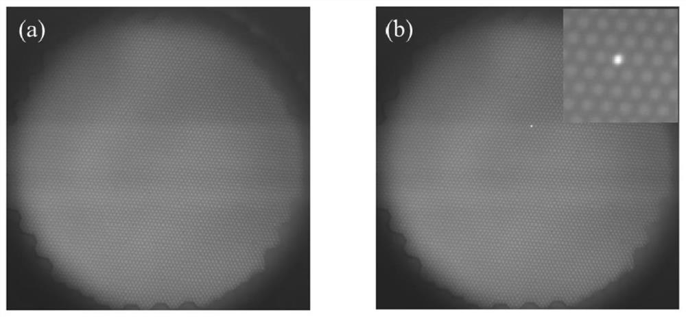
[0048] The present invention relates to transmission electron microscope sample holder systems with ultrafast time-resolved spectroscopy capabilities such as figure 1 As shown, it includes: a femtosecond laser 1, a beam expander collimator 2, a first flip mirror 3, a dispersion compensation element 4, a second flip mirror 5, a mirror 6, a first dichroic prism 7, and a microscope objective lens 8 , the sample bar 9 that fiber optic bundle is installed, white light source 10, the first lens 11, the second dichroic prism 12, the second lens 13, the third flip mirror 14, image acquisition device 15, optical filter 16, spectrometer 17, The third lens 18, the time-correlated single photon counter 19, the auxiliary optical imaging system 20; the detailed information of the sample rod part equipped with the fiber bundle is as attached figur...
Embodiment 2
[0053] This embodiment is used to illustrate the use method of the transmission electron microscope sample rod system of the present invention.
[0054] The specific implementation steps are as follows:
[0055] Step 1: The horizontally polarized light emitted by the femtosecond laser is first transformed into quasi-parallel light through the beam expander and collimator 2;
[0056] Step 2: passing the quasi-parallel femtosecond pulsed light obtained in step 1 through a grating pair to generate negative group velocity dispersion;
[0057] Step 3: focusing the broadened pulse light caused by the negative group velocity dispersion obtained in step 2 through the microscope objective lens 8 to the near end of the optical fiber bundle installed in the sample rod;
[0058] Step 4: irradiate the entire end face of the proximal end of the optical fiber bundle with the white light source 10 through the lens and the microscope objective lens 8;
[0059] Step 5: adjust the proximal end...
PUM
| Property | Measurement | Unit |
|---|---|---|
| Caliber | aaaaa | aaaaa |
Abstract
Description
Claims
Application Information
 - R&D
- Intellectual Property
- Life Sciences
- Materials
- Tech Scout
- Unparalleled Data Quality
- Higher Quality Content
- 60% Fewer Hallucinations
Browse by: Latest US Patents, China's latest patents, Technical Efficacy Thesaurus, Application Domain, Technology Topic, Popular Technical Reports.
© 2025 PatSnap. All rights reserved.Legal|Privacy policy|Modern Slavery Act Transparency Statement|Sitemap|About US| Contact US: help@patsnap.com


