
Complex permittivity test system and test method based on coaxial stripline resonator

A technology of complex permittivity and testing methods, applied in instruments, measuring devices, measuring electrical variables, etc., can solve the problems of low testing accuracy, large size of testing devices, difficult movement, etc., and achieve convenient adjustment of resonators and stable energy coupling. , the effect of high test accuracy

Active Publication Date: 2022-03-15
UNIV OF ELECTRONICS SCI & TECH OF CHINA
View PDF13 Cites 1 Cited by
  • Summary
  • Abstract
  • Description
  • Claims
  • Application Information

AI Technical Summary

Problems solved by technology

Zhang Y et al. (Zhang Y, Li E, Zhang J, et al. A broadband variable-temperature test system for complex permittivity measurements of solid and powder materials[J]. Review of entific Instruments, 2018, 89(2): 024701. ) in the article uses a cylindrical resonant cavity for testing, but this method has high requirements for the shape and size of the sample, and the liquid material needs to be loaded in a test tube and placed at a fixed position in the cavity, and there are large cavity volume, Disadvantages of cumbersome testing steps
The network parameter method is to calculate the reflection and transmission coefficients obtained by measuring the transmission network, and then obtain the complex dielectric constant of the material, such as Karim M.S.B.A (Karim M.S.B.A, Harafuji K, KonishiY, et al. Determination of Complex Permittivities of Layered Materials Using Waveguide Measurements [J]. IEEE Transactions on Microwave Theory and Techniques, 2014.) In the article, the complex permittivity of the sample to be tested is obtained by measuring the scattering parameters of samples in two different directions on the waveguide cross section; It has high shape and size requirements, and the sample needs to be placed in a rectangular waveguide, so liquid samples cannot be tested
At the same time, compared with the resonance method, because the network parameter method has a larger test error on the network parameters, the test accuracy is lower when testing low-loss materials.
Moreover, the above two methods all have the disadvantages of large test device size and difficulty in moving.

Method used


Image

  • Complex permittivity test system and test method based on coaxial stripline resonator
  • Complex permittivity test system and test method based on coaxial stripline resonator
  • Complex permittivity test system and test method based on coaxial stripline resonator

Examples


Embodiment 1

[0055] In this embodiment, the length (x) of the insulating dielectric film (3) is 4 mm, the width (y) is 2.5 mm, and the thickness (z) is 80 μm.

[0056] A method for testing the complex dielectric constant based on the testing system of the present invention, comprising the following steps:

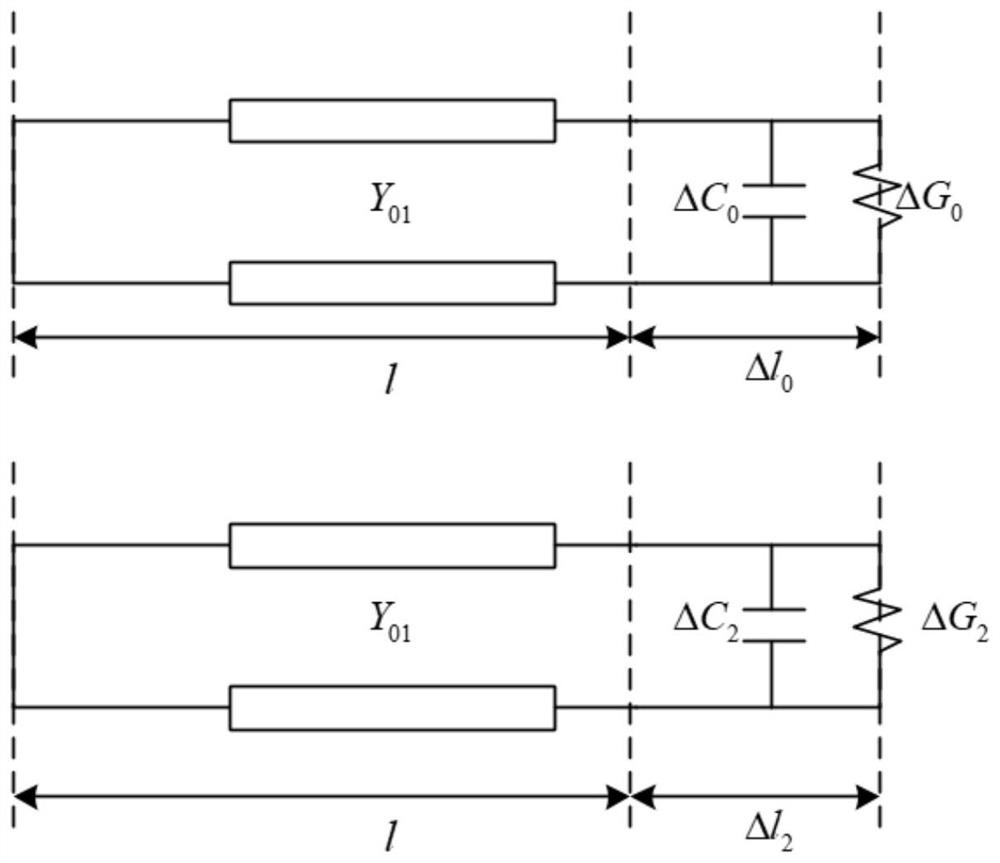
[0057] Step 1: Place 4 kinds of calibration standard samples (deionized water, normal saline, methanol, ethylene glycol) with known complex dielectric constants on the open end of the coaxial stripline resonator, and control the vector network analysis through the program-controlled computer The instrument records the resonant frequency f of the coaxial stripline resonator when the standard sample is loaded x and quality factor Q x , and record the resonant frequency f when no sample is loaded 0 and quality factor Q 0 ;

[0058] The values ​​of relative permittivity and loss tangent of four standard samples are as follows:

[0059]

[0060]

[0061] Step 2: The equivalent cir...


PUM


Abstract

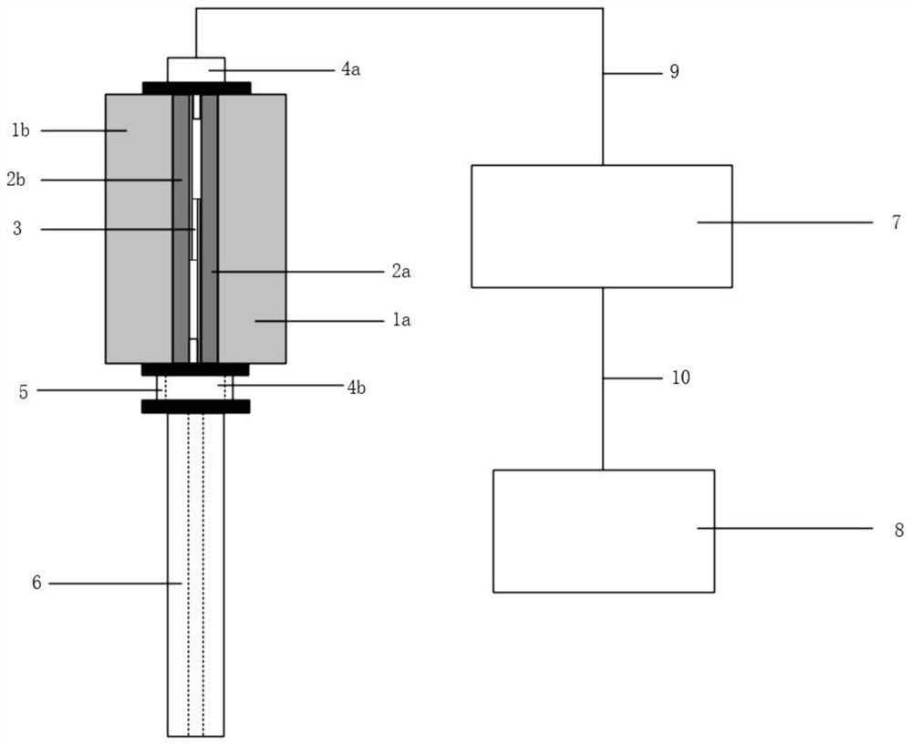
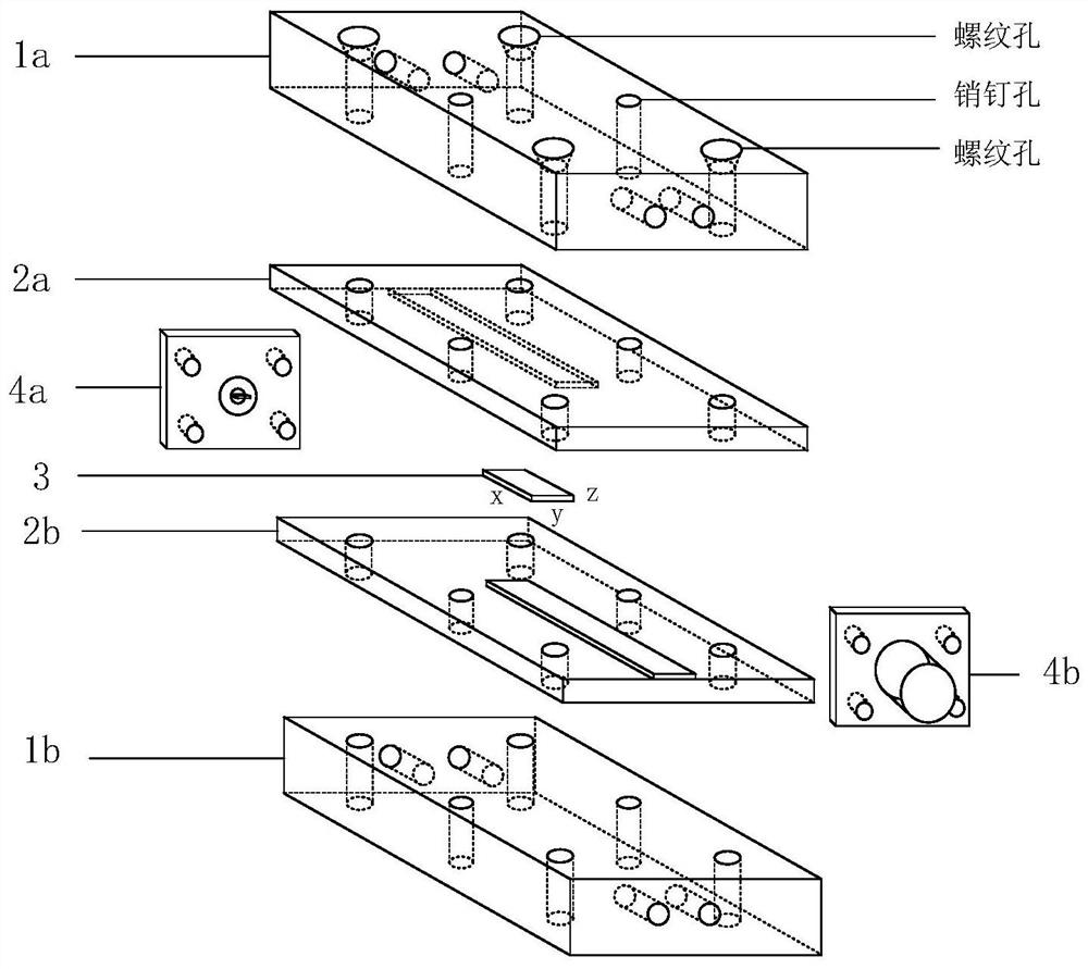
The invention provides a complex dielectric constant testing system and testing method based on a coaxial stripline resonator, belonging to the technical field of microwave material dielectric property testing. The test system of the present invention adopts a stripline capacitor and an open-terminal coaxial line to form a resonator with both ends open, and loads a sample on the open-circuit end of the open-terminal coaxial line of the test system to test the resonant frequency and quality factor, and then inverts to obtain The complex permittivity of the material. The test system of the present invention has the characteristics of small resonator size, stable energy coupling, hand-held test, small requirement on the shape and size of the sample to be tested, simple test operation and high test precision.

Description

technical field [0001] The invention belongs to the technical field of microwave material dielectric performance testing, and in particular relates to a complex dielectric constant testing system and testing method based on a coaxial stripline resonator. Background technique [0002] In the field of electronics, a variety of microwave materials are used in aerospace, civil communications, biomedicine, chemical industry and other fields, and the complex dielectric constant is a key parameter to describe the interaction mechanism between microwave materials and electromagnetic waves, and its accurate acquisition is of paramount importance. important. my country's microwave material electrical parameter testing technology has developed rapidly in recent years. In the electrical parameter testing of aerospace materials, communication substrate materials and non-destructive testing of materials, the testing methods are more diverse and can meet different testing needs. [0003] ...

Claims


Application Information

Patent Timeline
Patent Type & Authority Patents(China)
IPC IPC(8): G01R27/26
CPCG01R27/2623G01R27/2635
Inventor 彭亦童高冲苗润李恩郑虎张金涛
Owner UNIV OF ELECTRONICS SCI & TECH OF CHINA
Learn More