A vortex beam generation system, method and phase modulation combination device

A phase modulation and combination device technology, applied in the field of laser applications, can solve the problems of inability to flexibly meet processing requirements, inability to withstand kilowatt-level lasers, lack of flexibility and convenience, and achieve continuously adjustable size, long focal depth, and anti-misalignment. good effect

Active Publication Date: 2022-03-22
武汉先河激光技术有限公司
View PDF24 Cites 0 Cited by
  • Summary
  • Abstract
  • Description
  • Claims
  • Application Information

AI Technical Summary

Problems solved by technology

Due to the high price of the phase plate, more phase plates are needed to realize the flexible and adjustable vortex optical topology number. This method is too expensive and not flexible enough.
2. Based on the axicon lens to generate a combined ring-shaped spot, but due to the limitations of the axicon lens material and processing technology, the range of taper that can be processed is limited at present. When the taper is too small, there will be a large error, and for crystal materials, more It is very difficult to process the mirror surface composed of different taper surfaces, so the ring-shaped light spot output by the transmission type axicon prism has a relatively small adjustable range in terms of ring radius and other parameters, and it is difficult to output multiple ring-shaped combined light spots. Larger, unable to flexibly meet different processing requirements. In addition, the material of the axicon mirror also affects the size of the optical power that can be tolerated; 3. Based on the computational holography method to generate a combined annular spot, the computational holography can in principle be designed to produce a composite annular spot Any spot including the spot, but because the computational holography needs to be completed by a spatial light modulator, the spatial light modulator generally uses off-axis first-order diffracted light, coupled with loss and other factors, so the utilization rate of light energy is low, and It cannot withstand kilowatt-level lasers, so it is relatively less used; 4. The laser with adjustable spot mode based on optical fiber is used to generate combined annular spot. This method realizes the difficulty and cost of adjusting the spot distribution mode in the optical fiber. , because there is no adjustable external optical path, it lacks in flexibility and convenience of use

Method used


Image

  • A vortex beam generation system, method and phase modulation combination device
  • A vortex beam generation system, method and phase modulation combination device
  • A vortex beam generation system, method and phase modulation combination device

Examples


Embodiment 1

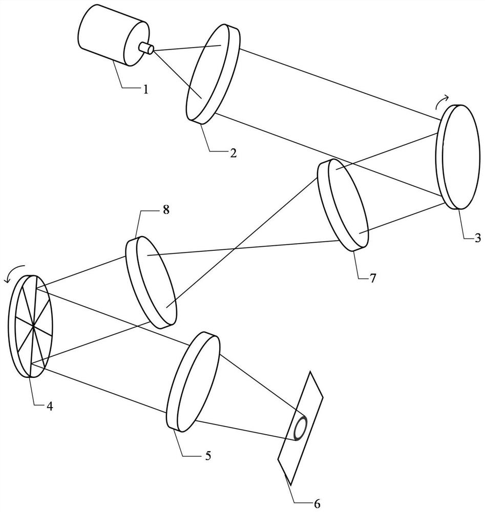
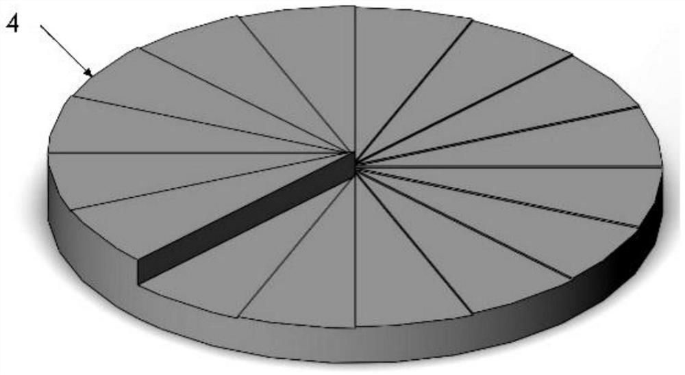
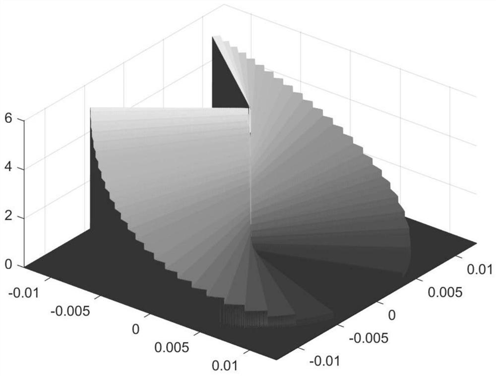
[0043] see figure 1 and figure 2 , this embodiment discloses a phase modulation combination device, including two helical-specific reflective spiral phase mirrors, and the phases of the two reflective spiral phase mirrors are respectively set to Aθ 2 and -Aθ 2 , A is a constant, which is used to control the variation range of the topological number of the obtained vortex beam. The topological number of the obtained vortex light takes all integers in the interval from 0 to 4Aπ, and θ is the azimuth angle with the center of the reflective spiral phase mirror as the origin , two reflective spiral phase mirrors are set on the optical path, the laser beam is reflected by the two reflective spiral phase mirrors in turn, and then the laser beam is attached with a spiral phase factor with a set topological number, and becomes an annular vortex beam with adjustable radius. The topological number of the resulting vortex beam is tuned by rotating one or both reflective spiral phase mi...

Embodiment 2

[0062] see figure 1 , this embodiment discloses a vortex beam generation system, including a collimation unit 2, a focusing unit 5, and the phase modulation combination device described in Embodiment 1, the phase modulation combination device is arranged between the collimation unit 2 and the focus unit on the optical path between 5;

[0063] The collimation unit 2 is used to collimate the input laser to obtain a collimated laser beam;

[0064] The two reflective spiral phase mirrors of the phase modulation combination device are used to sequentially reflect the collimated laser beam emitted by the collimation unit, and then attach a spiral phase factor with a set topological number, so that the laser beam becomes a radius-adjustable ring vortex beam;

[0065] The focusing unit 5 is used to focus the ring-shaped light beam emitted by the phase modulation combination device to obtain a light spot with ring-shaped energy distribution.

[0066] Further, before the collimation ...

Embodiment 3

[0074] This embodiment discloses a method for generating a vortex beam. The vortex beam generating system described in Embodiment 2 is adopted. The method includes the following steps: the laser emits a laser with a Gaussian distribution of light intensity, and the beam passes through a collimation unit for collimation. Straight processing to obtain a collimated laser beam;

[0075] The initial positions of the two reflective spiral phase mirrors of the phase modulation combination device are aligned. At this time, the phase modulation combination device has no phase modulation effect on the laser beam. Rotate one or two of the reflective spiral phase mirrors to adjust the resulting vortex beam. topological number, the angular difference between the two reflective spiral phase mirrors must be Integer multiples of , when the angle difference between the two reflective spiral phase mirrors is , the laser beam is sequentially reflected by two reflective spiral phase mirrors, a...


PUM


Abstract

The invention discloses a vortex beam generation system, method and phase modulation combination device. The phase modulation combination device of the invention includes two reflective spiral phase mirrors, and the phases of the two reflective spiral phase mirrors are respectively set to Aθ 2 and ‑Aθ 2 , A is a constant used to control the variation range of the topological number of the obtained vortex beam, θ is the azimuth with the center of the reflective spiral phase mirror as the origin, two reflective spiral phase mirrors are set on the optical path, and the laser beam passes through The two reflective spiral phase mirrors are reflected in turn and are attached with a spiral phase factor with a set topological number to become a ring-shaped vortex beam. The angle of the two reflective spiral phase mirrors is controlled by rotating one or two reflective spiral phase mirrors. difference, to adjust the topological number of the resulting vortex beam. The present invention designs a pair of reflective spiral phase mirrors with opposite spin directions, and generates a vortex beam with an adjustable topology number through rotation after combination, which is suitable for various laser processes such as laser cutting, welding, and drilling.

Description

technical field [0001] The invention belongs to the field of laser applications, and more specifically, the invention relates to a vortex beam generation system, method and phase modulation combination device. Background technique [0002] The energy distribution of ordinary Gaussian beams decreases from the center to the edge, and most of the energy is concentrated in the central area. In the field of laser processing, especially in the fields of laser welding, cutting, cladding, etc., ablation and other phenomena may occur if the center energy is too high, and due to insufficient energy at the edge, when performing deep processing such as laser cutting, the deeper the processing depth, the edge The energy is even more insufficient, which leads to uneven cutting section, which significantly limits the processing quality and processing accuracy. [0003] In view of the above problems, the commonly used treatment method is to change the Gaussian distribution of light spots i...

Claims


Application Information

Patent Timeline
Patent Type & Authority Patents(China)
IPC IPC(8): G02B26/06G02B27/09
CPCG02B26/06G02B27/0927G02B27/0977G02B27/0944
Inventor 徐家明秦应雄张兰天段光前
Owner 武汉先河激光技术有限公司
Why Eureka
Try Eureka