Eureka AIR delivers breakthrough ideas for toughest innovation challenges, trusted by R&D personnel around the world.

A kind of preparation method of semiconductor device

A semiconductor and device technology, applied in the field of semiconductor preparation, to achieve the effects of small process fluctuation, high yield and low cost

Active Publication Date: 2021-04-30
四川省华盾防务科技股份有限公司
View PDF16 Cites 0 Cited by
  • Summary
  • Abstract
  • Description
  • Claims
  • Application Information

AI Technical Summary

Problems solved by technology

[0003] In order to solve the problem that nanoscale photolithography is required in the preparation of the gate of the existing high-frequency millimeter-wave and terahertz chips, the present invention provides a method for preparing a semiconductor device, which realizes the preparation of the gate by deposition and etching, and prepares the gate There is no need for a photolithography machine in extreme cases, the process fluctuation is small, it has the characteristics of low cost, high efficiency, and high yield, and can be widely used in the production and manufacture of high-frequency millimeter wave and terahertz chips

Method used


Image

  • A kind of preparation method of semiconductor device
  • A kind of preparation method of semiconductor device
  • A kind of preparation method of semiconductor device

Examples


Embodiment 1

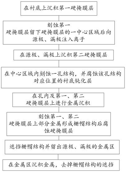
[0061] like figure 1 The shown preparation method of a semiconductor device can be widely used in the production of high-frequency millimeter-wave and terahertz chips, and the specific method includes the following steps:

[0062] Step S01: depositing a first hard mask layer on a substrate, the substrate comprising an epitaxial wafer 11 and a passivation layer 12 deposited on the epitaxial wafer 11;

[0063] Step S02: etching the first hard mask layer to leave the central region of the first hard mask layer, namely etching away the peripheral region of the first hard mask layer, and then implanting ions into the source and drain electrodes;

[0064] Step S03 : depositing a second hard mask layer on the source and drain electrodes after the ions have been implanted, that is, depositing a second hard mask layer on the outer edge of the first hard mask layer;

[0065] Step S04: etching a hole structure on the central region of the first hard mask layer, placing the hole structur...

Embodiment 2

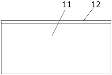
[0071] Based on the principle of the above-mentioned Embodiment 1, this embodiment discloses a specific implementation manner, refer to Figure 2-Figure 19 . The substrate includes an epitaxial wafer 11 and a passivation layer 12 , and the substrate can be obtained by directly depositing the passivation layer 12 on the epitaxial wafer 11 . The epitaxial wafer needs to be cleaned in advance.

[0072] like figure 2 As shown, a first hard mask layer is deposited on a substrate comprising gallium nitride or gallium arsenide, and the passivation layer may be silicon dioxide or silicon nitride. The thickness of the passivation layer is at the nanometer level, such as 20 nm, 30 nm or other thickness, and the setting can be adjusted according to the actual situation. In this embodiment, 20 nm is taken as an example.

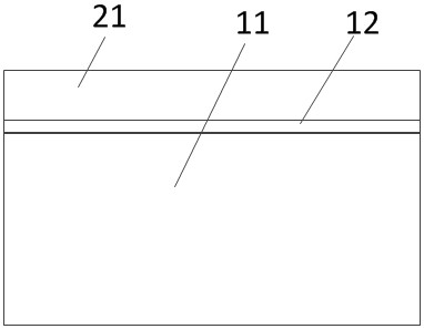
[0073] like image 3 As shown, a first medium 21 is deposited on the passivation layer 12 of the substrate. The first medium 21 can be silicon dioxide or silicon ni...


PUM


Abstract

The invention relates to a method for preparing a semiconductor device, comprising the following steps: depositing a first hard mask layer on a substrate; etching the first hard mask layer to leave a central region, and then implanting ions into the source and drain electrodes; Depositing a second hard mask layer on the outer edge of the first hard mask layer; etching a hole structure on the central area of ​​the first hard mask layer, and etching the substrate passivation layer at the corresponding position of the hole structure; Carry out metal deposition on the first hard mask layer and the second hard mask layer; etch the hard mask layer after etching the first hard mask layer and part of the metal on the second hard mask layer to form a gate cap structure; The cap structure exposes the metal regions of the source and drain electrodes; metal is deposited on the metal region to remove the shielding of the gate cap structure. The method of this scheme realizes gate preparation through deposition and etching, and does not need a photolithography machine when preparing the gate. The process fluctuation is small, and it has the characteristics of low cost, high efficiency, and high yield, and can be widely used in high-frequency mm It involves the production and manufacture of terahertz chips.

Description

technical field [0001] The invention belongs to the technical field of semiconductor preparation, and in particular relates to a method for preparing a semiconductor device. Background technique [0002] With the continuous development of the electronic information industry, the preparation technology of integrated circuits has attracted more and more attention. High-frequency semiconductor radio frequency devices have very strict requirements on the size of the device, especially the gate length, which requires a nanoscale photolithography machine for fabrication. However, the lithography scale of the lithography machine is limited by various technologies such as light sources, and it is difficult to achieve nanoscale grid lithography; and the use of a lithography machine to achieve grid lithography requires extremely high process costs and serious environmental problems Sensitivity, prone to process fluctuations, resulting in a decline in yield. Contents of the inventio...

Claims


Application Information

Patent Timeline
Patent Type & Authority Patents(China)
IPC IPC(8): H01L21/027H01L21/306
CPCH01L21/027H01L21/30604
Inventor 黄洪云
Owner 四川省华盾防务科技股份有限公司
Why Eureka
Eureka Blog
Learn More