Thin-gauge martensitic steel strip and manufacturing method thereof

A martensitic steel and manufacturing method technology, applied in the direction of manufacturing tools, heat treatment process control, heat treatment equipment, etc., can solve problems such as uneven performance of strip steel, unstable product performance, and uneven microstructure

Active Publication Date: 2021-03-19
BAOSHAN IRON & STEEL CO LTD
View PDF16 Cites 3 Cited by
  • Summary
  • Abstract
  • Description
  • Claims
  • Application Information

AI Technical Summary

Problems solved by technology

At the same time, the contact of high-temperature strip steel with cooling water will cause many problems: first, water spots (rust spots) will be formed on the surface of the strip steel, which will affect the surface quality; second, the cooling water used for laminar flow cooling or spray cooling It is easy to cause uneven local cooling on the surface of the strip, resulting in uneven microstructure inside the strip, resulting in uneven properties of the strip and affecting product quality; third, uneven local cooling on the surface of the strip will cause deterioration of the shape of the strip , affecting the shape quality
[0014] However, due to the rapid solidification process characteristics of thin strip continuous casting, the p...

Method used


Image

  • Thin-gauge martensitic steel strip and manufacturing method thereof
  • Thin-gauge martensitic steel strip and manufacturing method thereof
  • Thin-gauge martensitic steel strip and manufacturing method thereof

Examples


Embodiment Construction

[0079] The present invention will be further illustrated below with examples, but these examples are by no means any limitation to the present invention. Any changes made by those skilled in the art in the implementation of the present invention under the inspiration of this specification will fall within the protection scope of the claims of the present invention.

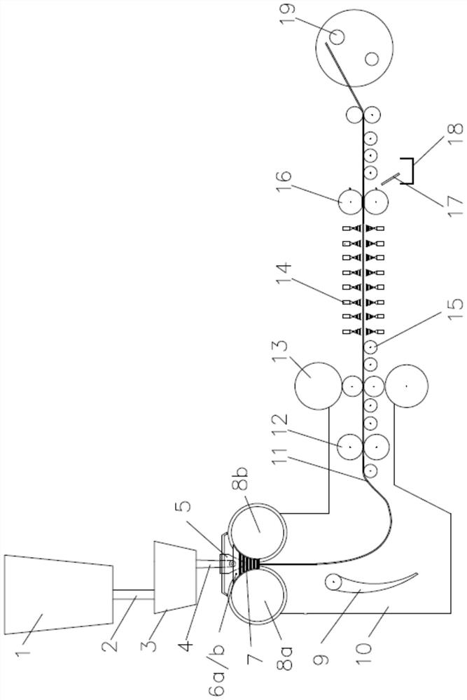
[0080] see figure 1 , the molten steel conforming to the design of the chemical composition of the present invention is poured directly through the ladle 1, through the ladle long nozzle 2, the tundish 3, the submerged nozzle 4 and the flow distributor 5 in a crystallization chamber that is made of two relatively rotating and capable of rapid cooling. In the molten pool 7 surrounded by the rollers 8a, 8b and the side sealing plate devices 6a, 6b, the molten steel solidifies on the circumferential surface where the crystallization rollers 8a, 8b rotate, and then forms a solidified shell and gradually grows at the p...


PUM


Abstract

The invention discloses a thin-gauge martensitic steel strip and a manufacturing method thereof. The thin-gauge martensitic steel strip is prepared from the following components in percentage by weight: 0.16-0.26% of C, 0.1-0.5% of Si, 0.4-1.7% of Mn, less than or equal to 0.02% of P, less than or equal to 0.007% of S, 0.004-0.010% of N, less than 0.001% of Als, 0.007-0.020% of total oxygen [O]<T>, and the balance of Fe and other inevitable impurities. Meanwhile, the thin-gauge martensitic steel strip meets the following requirements: the thin-gauge martensitic steel strip contains one or twoof 0.1-0.6% of Cu or 0.005-0.04% of Sn; the thin-gauge martensitic steel strip contains one or two of 0.01-0.08% of Nb and 0.1-0.4% of Mo; and Mn/S is greater than 250. The manufacturing method comprises the following steps: smelting molten steel by using residual Sn, Cu and other elements in scrap steel, and selectively adding Nb/Mo and other microalloy elements into the steel; in the smelting process, controlling the alkalinity of slag, the type and melting point of inclusions in the steel, the content of free oxygen in the molten steel and the content of acid-soluble aluminum Als; and thencarrying out double-roller strip continuous casting to cast a cast strip, and carrying out online hot rolling and gas atomization rapid cooling to obtain the thin-gauge martensitic steel strip.

Description

technical field [0001] The invention belongs to the continuous casting process, and in particular relates to a thin-gauge martensitic steel strip and a manufacturing method thereof. Background technique [0002] In the traditional steel production process, tin (Sn) and copper (Cu) are typical residual or harmful elements in steel. It is very difficult and expensive to fully remove Sn and Cu in the steelmaking process. Once the steel contains Sn , Cu, basically cannot be completely eliminated, and the content of Sn and Cu can only be reduced by diluting molten steel, which all lead to an increase in the cost of smelting steel products. [0003] In recent years, due to the continuous recycling of steel scrap, there are more and more scrap steel resources, and the electricity price has also continued to decrease. Domestic short-process electric furnace steelmaking based on scrap steel is increasingly rising, resulting in the gradual increase in the content of residual elements ...

Claims


Application Information

Patent Timeline
IPC IPC(8): C22C38/16C22C38/12C22C38/06C22C38/04C22C38/02C22C33/04B22D11/06C21D1/74C21D8/02C21D11/00C21D1/00
CPCC22C38/16C22C38/12C22C38/06C22C38/04C22C38/02C22C38/008C22C38/002C22C38/001C22C33/04B22D11/0622B22D11/0682C21D1/74C21D8/0205C21D8/0226C21D11/005C21D1/00C21D2211/002C21D2211/008
Inventor 吴建春方园
Owner BAOSHAN IRON & STEEL CO LTD
Why Eureka
Try Eureka