Microwave rock breaking drilling device

A drilling and rock-breaking technology, applied in drilling equipment, drill bits, earthwork drilling and production, etc., can solve the problems of drilling equipment such as lack of economic competitiveness, failure to exert full production capacity, and inability to adapt to drilling requirements, etc., to achieve increased microwave effect, improve rock breaking efficiency, and reduce drilling tool loss

Pending Publication Date: 2021-03-19
SHENZHEN UNIV
View PDF0 Cites 3 Cited by
  • Summary
  • Abstract
  • Description
  • Claims
  • Application Information

AI Technical Summary

Problems solved by technology

[0003] Drilling is also known as percussion drilling. The power drive device drives the wire rope and the drill bit to produce up and down impact to achieve the effect of rock breaking. This method has the disadvantages of slow drilling speed and low efficiency, and cannot meet the requirements of deep drilling and complex formation drilling.
The working principle of rotary drilling is to rotate the drill bit under a certain axial pressure (weight-on-bit) to cut or roll the rock into debris. Compared with percussion drilling, it can greatly improve drilling efficiency and adapt to various complex downhole formations. It has become the current mainstream drilling method, but the disadvantage is that when the rock hardness is high, the rock breaking speed will largely depend on the hardness of the drill bit itself. When breaking rock with high hardness, the drilling equipment is not economical due to the wear of the cutterhead. competitiveness, or not operating at full production capacity due to increased rock hardness and maintenance
[0004] The two mainstream drilling methods in the industry both have bottlenecks that are difficult to break through to a certain extent, which leads to problems such as high drilling costs and low drilling efficiency

Method used


Image

  • Microwave rock breaking drilling device
  • Microwave rock breaking drilling device
  • Microwave rock breaking drilling device

Examples


Embodiment Construction

[0046] In order to make the object, technical solution and advantages of the present invention more clear and definite, the present invention will be further described in detail below with reference to the accompanying drawings and examples. It should be understood that the specific embodiments described here are only used to explain the present invention, not to limit the present invention.

[0047] In the description of the present invention, it should be understood that the orientation or positional relationship indicated by the terms "center", "upper", "lower", "front", "rear", "left", "right" etc. are based on The orientations or positional relationships shown in the drawings are only for the convenience of describing the present invention and simplifying the description, and do not indicate or imply that the referred devices or components must have a specific orientation, be constructed and operated in a specific orientation, and therefore cannot be understood as Limitat...


PUM


Abstract

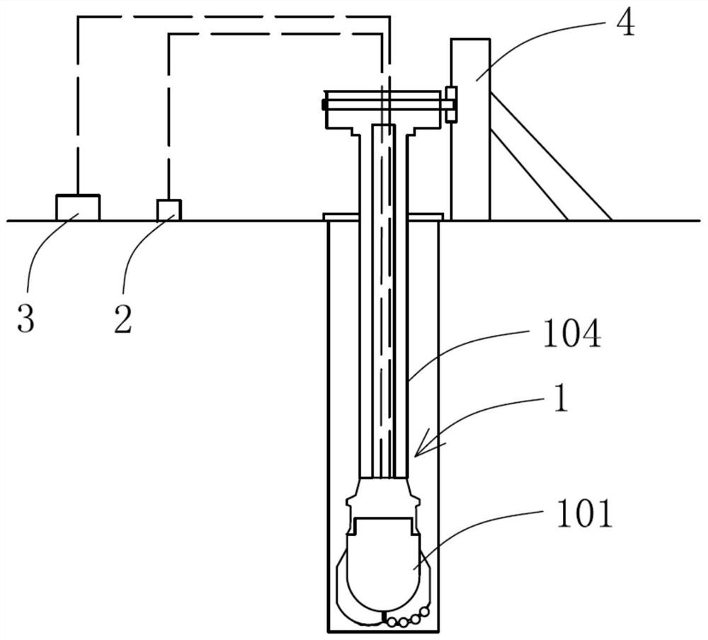
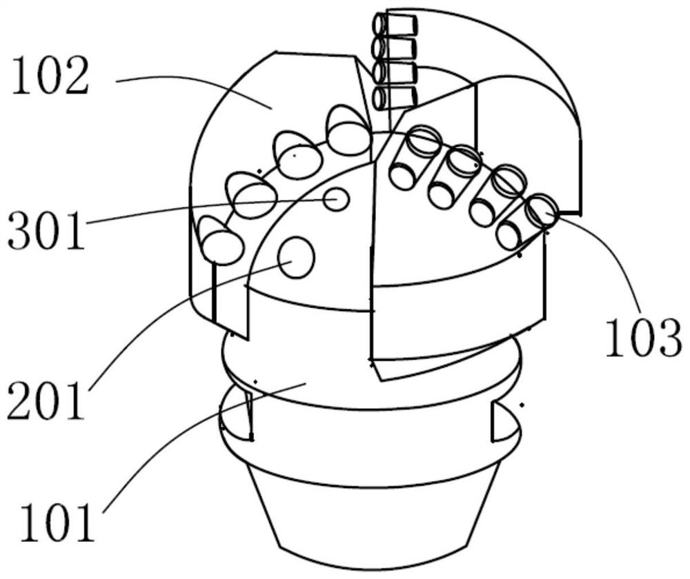
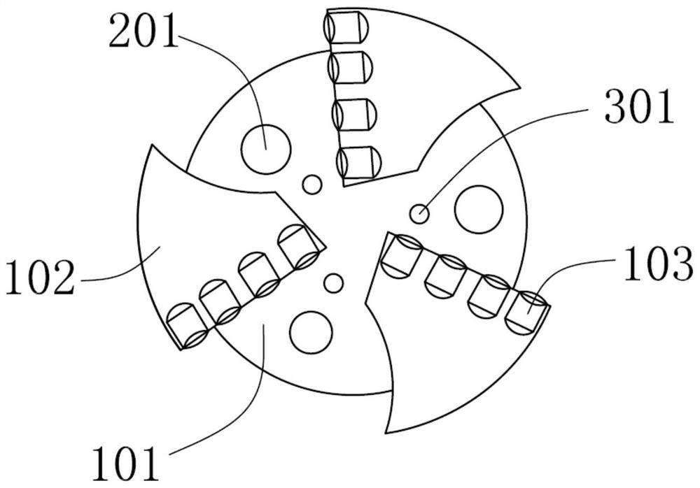
The invention provides a microwave rock breaking drilling device. The microwave rock breaking drilling device comprises an integrated drill bit assembly, a microwave generation assembly and a water jetting dust removal assembly. The integrated drill bit assembly comprises a drill bit body, a cutter head and cutting teeth. The cutter head and the cutting teeth are arranged on the drill bit body. The microwave generation assembly comprises microwave emission holes, and the microwave emission holes are formed in the drill bit body and communicate with the outside. The water jetting dust removal assembly comprises water jetting holes, and the water jetting holes are formed in the drill bit body and communicate with the outside. On the one hand, when hard rock drilling is carried out, the microwave generation assembly is used for performing microwave action on rock, the rock temperature field is changed to soften the rock, the rock strength is reduced, drill bit abrasion is reduced, and therock breaking efficiency is improved; and on the other hand, the influence of mud, dust and the like on the microwave emission holes is effectively solved through a water jetting cleaning system, theeffect of reducing the temperature of the drill bit can be achieved, the rock wave absorbing capacity is enhanced, the microwave effect is improved, efficiency is improved, and losses are reduced.

Description

technical field [0001] The invention relates to the technical field of drilling, in particular to a drilling and rock-breaking device, in particular to a drilling device that utilizes microwaves to soften rocks and assist in rock-breaking. Background technique [0002] Drilling refers to the working process of using mechanical equipment or manpower to drill the formation into holes from the ground. It is usually used in the exploration or development of liquid and gaseous minerals such as oil and natural gas to drill boreholes and large-diameter water supply wells. It is widely used in national economic construction. At present, the commonly used drilling methods are divided into sudden drilling and rotary drilling. [0003] Drilling is also called percussion drilling. The power drive device drives the steel wire rope and the drill bit to produce up-and-down impact to achieve the effect of rock breaking. This method has the disadvantages of slow drilling speed and low effic...

Claims


Application Information

Patent Timeline
Patent Type & Authority Applications(China)
IPC IPC(8): E21B7/00E21B10/42E21B10/54E21B10/60
CPCE21B7/00E21B10/42E21B10/54E21B10/60
Inventor 高明忠王轩李铭辉杨本高温翔越杨钊颖
Owner SHENZHEN UNIV
Why Eureka
Try Eureka