Dust-removing and sulfur-removing device for chemical high-temperature waste gas

A high-temperature waste gas and chemical technology, applied in chemical instruments and methods, gaseous effluent wastewater treatment, water/sludge/sewage treatment, etc., can solve problems such as high energy consumption of desulfurization devices, health impact, and inability to treat waste gas. Achieve the effects of increasing desulfurization efficiency, increasing contact time, and reducing waste

Pending Publication Date: 2021-03-30
钱珍珍
View PDF0 Cites 0 Cited by
  • Summary
  • Abstract
  • Description
  • Claims
  • Application Information

AI Technical Summary

Problems solved by technology

And automobile exhaust, among them, the sulfur content in chemical waste gas is also very high. The direct discharge of sulfur into the atmosphere will have a great impact on the environment and the health of the masses. Therefore, chemical waste gas needs to be desulfurized before it is discharged. treatment, so as to avoid pollution to the atmosphere, but the desulfurization device currently in use cannot treat the exhaust gas well, and the energy consumption of the desulfurization device is relatively high. Therefore, we propose a chemical high-temperature waste gas dedusting and desulfurization device

Method used


Image

  • Dust-removing and sulfur-removing device for chemical high-temperature waste gas
  • Dust-removing and sulfur-removing device for chemical high-temperature waste gas
  • Dust-removing and sulfur-removing device for chemical high-temperature waste gas

Examples


Embodiment Construction

[0021] The following will clearly and completely describe the technical solutions in the embodiments of the present invention with reference to the accompanying drawings in the embodiments of the present invention. Obviously, the described embodiments are only some, not all, embodiments of the present invention.

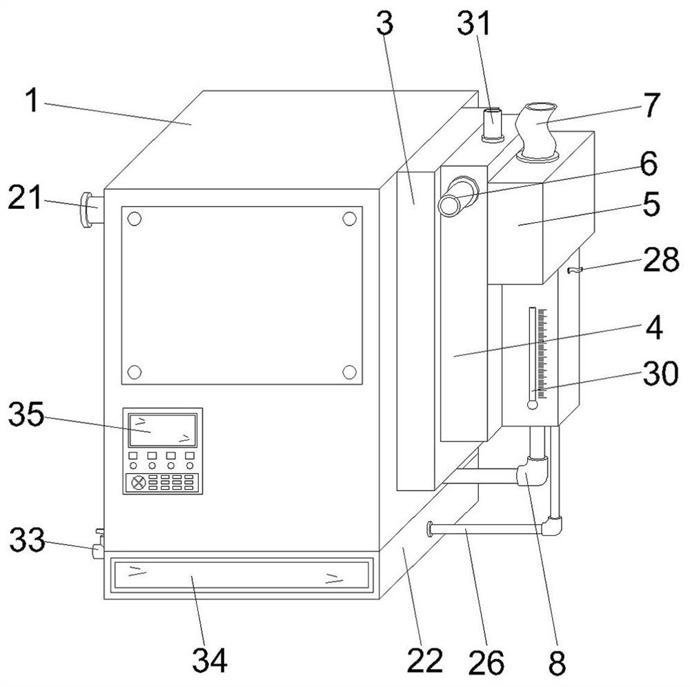
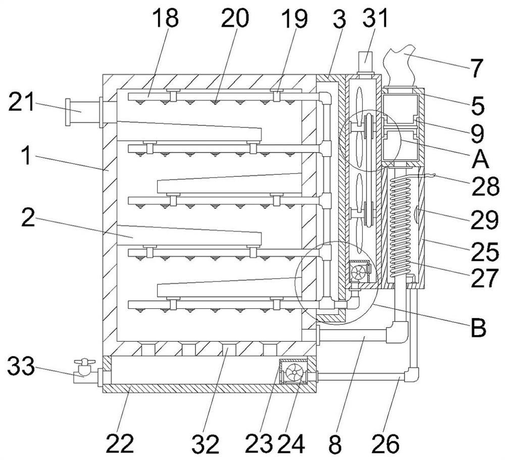
[0022] see Figure 1 to Figure 5 , the present invention provides a technical solution: a chemical high-temperature waste gas dedusting and desulfurization device, including a desulfurization treatment box 1, and inner guide plates 2 are installed on both sides corresponding to the inside of the desulfurization treatment box 1, and one side of the desulfurization treatment box 1 The side pipe installation box 3 is fixedly installed, and the side of the side pipe installation box 3 away from the inner guide plate 2 is fixedly installed with a side stirring water tank 4, and the side of the side stirring water tank 4 away from the side pipe installation box 3 is fixedly...


PUM


Abstract

The invention discloses a dust-removing and sulfur-removing device for chemical high-temperature waste gas, belonging to the technical field of sulfur removal of waste gas. The device comprises a desulfurization treatment box, wherein inner guide plates are installed on the two corresponding inner sides of the desulfurization treatment box, and a side pipeline installation box is fixedly installedon one side of the desulfurization treatment box. The device of the invention has the beneficial effects that by utilizing airflow generated when waste gas is injected into the dust-removing and sulfur-removing device, a rotating blade, a second rotating mounting column and stirring blades are driven to rotate, so reagent liquid stored in a side stirring water tank is conveniently stirred, and water and a desulfurizing agent are stirred and mixed more uniformly; then the reagent liquid which has been uniformly mixed is sprayed out by utilizing a spraying head, and contact time between the reagent liquid and industrial waste gas can be prolonged by utilizing blocking of the multiple inner guide plates, so desulfurization efficiency is improved; and compared with a currently used desulfurization device, kinetic energy in the waste gas is fully utilized, and resource waste is reduced.

Description

technical field [0001] The invention relates to the technical field of waste gas desulfurization, in particular to a high-temperature chemical waste gas dedusting and desulfurization device. Background technique [0002] Chemical waste gas refers to the poisonous and harmful gas discharged from chemical plants in chemical production. Chemical waste gas often contains many types of pollutants, complex physical and chemical properties, and different toxicity, which seriously pollutes the environment and affects human health. The composition of chemical waste gas produced by different chemical production industries varies greatly. For example, the waste gas produced by the chlor-alkali industry mainly contains chlorine, hydrogen chloride, vinyl chloride, mercury, acetylene, etc., and the waste gas produced by the nitrogen fertilizer industry mainly contains nitrogen oxides, urea dust, carbon monoxide, ammonia, sulfur dioxide, methane, etc. And automobile exhaust, among them, ...

Claims


Application Information

Patent Timeline
IPC IPC(8): B01D53/79B01D53/50B01D53/34B01D47/06C02F1/16C02F103/18
CPCB01D53/79B01D53/50B01D47/06B01D53/346C02F1/16C02F2103/18
Inventor 钱珍珍
Owner 钱珍珍
Why Eureka
Try Eureka