Free space type distributed optical fiber Raman temperature sensor

A distributed optical fiber and temperature sensor technology, applied in the field of optical communication, can solve problems such as low reliability, low transmission speed, and low coupling efficiency, and achieve improved stability and reliability, high layout integration, and low coupling efficiency Effect

Inactive Publication Date: 2021-04-02
武汉华瑞光联科技有限公司
View PDF5 Cites 0 Cited by
  • Summary
  • Abstract
  • Description
  • Claims
  • Application Information

AI Technical Summary

Problems solved by technology

High cost, complex structure, low coupling efficiency, large loss, low transmission speed, and low reliability

Method used


Image

  • Free space type distributed optical fiber Raman temperature sensor

Examples


Embodiment Construction

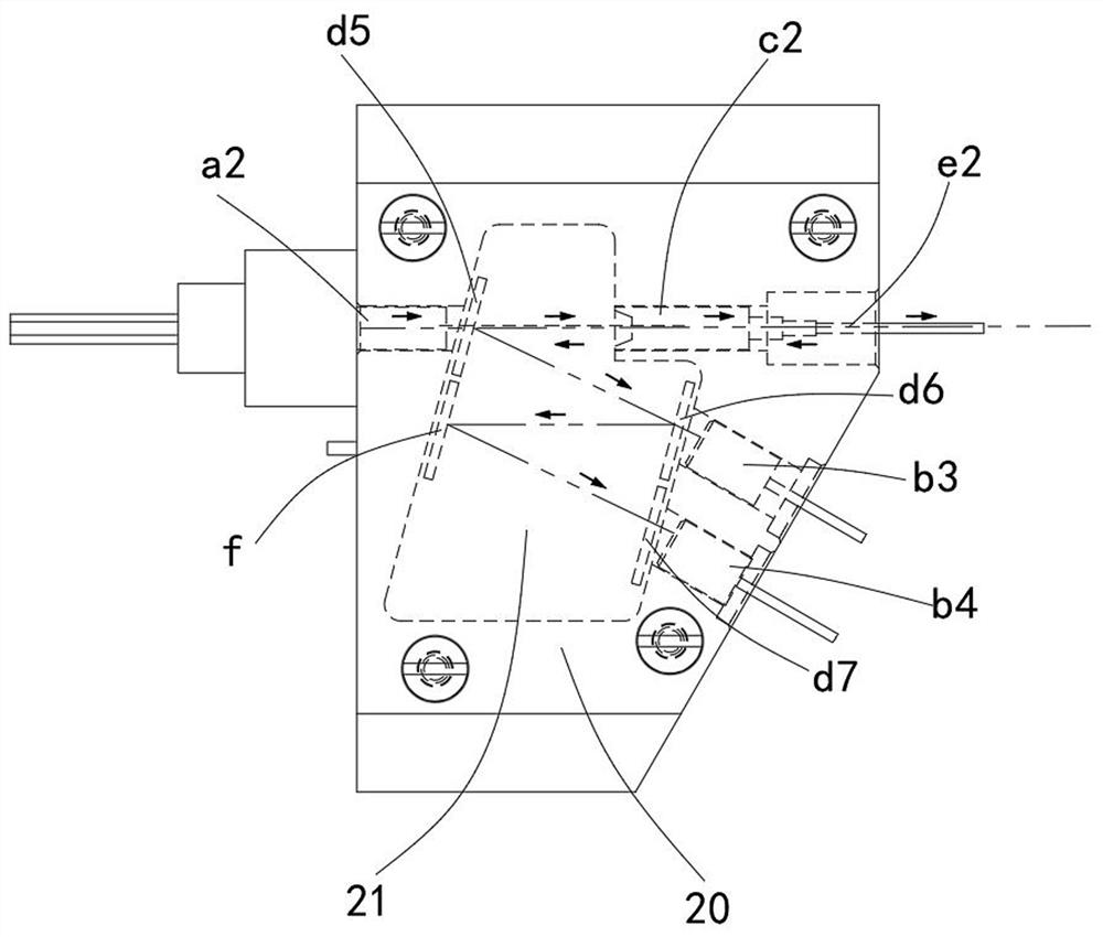
[0026] In order to make the object, technical solution and advantages of the present invention clearer, the present invention will be further described in detail below in conjunction with the accompanying drawings and embodiments. It should be understood that the specific embodiments described here are only used to explain the present invention, not to limit the present invention.

[0027] It should be noted that when an element is referred to as being “fixed” to another element, it can be directly on the other element or there can also be an intervening element. When an element is referred to as being "connected to" another element, it can be directly connected to the other element or intervening elements may also be present. The terms "vertical," "horizontal," "left," "right," and similar expressions are used herein for purposes of illustration only and are not intended to represent the only embodiments.

[0028] Unless otherwise defined, all technical and scientific terms ...


PUM


Abstract

The invention discloses a free space type distributed optical fiber Raman temperature sensor. The sensor comprises a second laser, a third avalanche optical diode, a fourth avalanche optical diode, asecond collimator, a fifth thin film optical filter, a sixth thin film optical filter and an optical reflector, and the fifth thin film optical filter, the sixth thin film optical filter, the sevenththin film optical filter and the optical reflector are parallel to one another. According to the invention, a free space technology is adopted, and optical signal transmission is carried out through air by using a separated film optical filter and an independent 1. sealed space; after optical fiber cascade media are removed, optical signals are directly transmitted through the air, loss of the optical signals is greatly reduced, the signals are better, the transmission speed is high, different from optical fiber cascade adopted by a traditional distributed optical fiber temperature sensor system, space is saved, constant temperature is provided by a semiconductor refrigerator, and stability and reliability of the system are improved.

Description

technical field [0001] The invention relates to the technical field of optical communication, in particular to a free-space distributed optical fiber Raman temperature sensor. Background technique [0002] The distributed optical fiber temperature sensor system uses the temperature effect of optical fiber back Raman scattering. The temperature field of each point in the space where the optical fiber is located modulates the light intensity of back Raman scattering in the optical fiber. By detecting the change of light intensity at each point on the optical fiber Realize continuous monitoring of temperature changes at any point on the optical fiber and locate the temperature field. [0003] The existing distributed optical fiber temperature sensor system includes a laser generator, an optical fiber with a bidirectional coupler, an optical wavelength division multiplexer, two avalanche photodiodes, two amplifiers, a signal acquisition card and a computer. The optical pulse en...

Claims


Application Information

Patent Timeline
Patent Type & Authority Applications(China)
IPC IPC(8): G01K11/324G02B5/20
CPCG01K11/32G02B5/20
Inventor 张学湘阳红刚王一华
Owner 武汉华瑞光联科技有限公司
Why Eureka
Try Eureka