Efficient RTO waste gas removal system and method

A waste gas and high-efficiency technology, applied in the RTO waste gas efficient removal system and removal field, can solve the problems of poor treatment effect and incomplete treatment of organic waste gas, so as to reduce the possibility of explosion, improve safety and reliability, and reduce waste gas residue Effect

Inactive Publication Date: 2021-04-09
苏州市中天新工业技术有限公司
View PDF0 Cites 0 Cited by
  • Summary
  • Abstract
  • Description
  • Claims
  • Application Information

AI Technical Summary

Problems solved by technology

[0003] In order to overcome the defects in the prior art, the embodiment of the present invention provides a high-efficiency removal system and method for RTO waste gas, which has a simple structure and is easy to use, can prevent the untreated waste gas from being discharged directly, and improve the treatment effect of the waste gas , to overcome the defects of incomplete treatment of organic waste gas and poor treatment effect in the prior art

Method used


Image

  • Efficient RTO waste gas removal system and method
  • Efficient RTO waste gas removal system and method
  • Efficient RTO waste gas removal system and method

Examples


Embodiment Construction

[0036] The following will clearly and completely describe the technical solutions in the embodiments of the present invention with reference to the accompanying drawings in the embodiments of the present invention. Obviously, the described embodiments are only some, not all, embodiments of the present invention. Based on the embodiments of the present invention, all other embodiments obtained by persons of ordinary skill in the art without making creative efforts belong to the protection scope of the present invention.

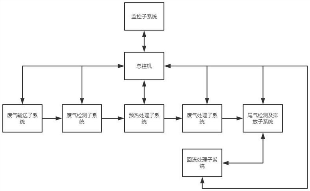
[0037] refer to figure 1 and figure 2 , the embodiment of the present application discloses: an RTO waste gas efficient removal system, including a master control machine, the master control machine is connected with a waste gas conveying subsystem, a waste gas detection subsystem, a preheating treatment subsystem, a waste gas Treatment subsystem, tail gas detection and emission subsystem and return flow treatment subsystem, of which:

[0038] The waste gas...


PUM


Abstract

The invention relates to an efficient RTO waste gas removal system. The system comprises a master control machine, and the master control machine is connected with a waste gas conveying subsystem, a waste gas detection subsystem, a preheating treatment subsystem, a waste gas treatment subsystem, a tail gas detection and discharge subsystem and a backflow treatment subsystem through serial communication lines; due to the arrangement of the waste gas detection subsystem, the concentration of waste gas can be detected and adjusted before the waste gas is treated, so that the possibility of explosion of combustible gas in the waste gas is reduced, and the safety and reliability in the treatment process are improved; and the waste gas can be preheated through the preheating treatment subsystem before combustion treatment of the waste gas; the energy consumption in the waste gas heating process is reduced, and the energy utilization efficiency is improved; and the waste gas treatment effect can be effectively improved through the tail gas detection and discharge subsystem and the backflow treatment subsystem, waste gas residues are reduced, and secondary pollution to the environment is avoided.

Description

technical field [0001] The invention relates to the technical field of environmental protection equipment, in particular to an efficient removal system and method for RTO waste gas. Background technique [0002] The existing catalytic oxidation combustion device generally includes a catalytic fan, an electric heating chamber, a heat exchanger, a catalytic oxidation chamber (catalyst), a flame arrester, a pipeline, and an explosion vent. The existing catalytic oxidation process is to directly introduce medium and high concentration organic waste gas into the catalytic oxidation combustion device. In the initial stage, the temperature needs to be raised to the temperature required by the reaction through an electric heater, and the exhaust gas is oxidized under the action of the catalyst in the catalytic oxidation chamber. The exothermic reaction generates harmless water and carbon dioxide, and the heat released after decomposition heats the organic waste gas entering the cata...

Claims


Application Information

Patent Timeline
IPC IPC(8): F23G7/06F23G5/02F23G5/16F23G5/46F23G5/50F23G5/44
CPCF23G5/02F23G5/16F23G5/44F23G5/46F23G5/50F23G7/06F23G2202/103F23G2206/10F23G2209/14F23G2900/50213F23G2900/55
Inventor 俞志耘许晓清欧阳军袁俊环
Owner 苏州市中天新工业技术有限公司
Why Eureka
Try Eureka