Laser radar system, optical signal receiving and processing device and optical signal receiving and processing method

A laser radar and processing device technology, applied to radio wave measurement systems, instruments, etc., can solve the problems of large environmental impact, difficult to overcome signals, and high frequency of laser radar systems, achieve small size, simple system design, and improve signal-to-noise ratio Effect

Pending Publication Date: 2021-04-27
哈尔滨新光光电科技股份有限公司
View PDF6 Cites 5 Cited by
  • Summary
  • Abstract
  • Description
  • Claims
  • Application Information

AI Technical Summary

Problems solved by technology

[0004] One purpose of the present invention is to solve the defects that the existing laser radar system is greatly affected by the envi

Method used


Image

  • Laser radar system, optical signal receiving and processing device and optical signal receiving and processing method
  • Laser radar system, optical signal receiving and processing device and optical signal receiving and processing method
  • Laser radar system, optical signal receiving and processing device and optical signal receiving and processing method

Examples


Embodiment approach 1

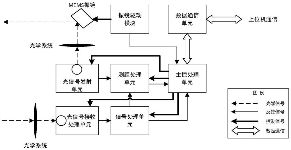
[0031]This embodiment provides a laser radar system, such asfigure 1 As shown, including:

[0032]The optical signal transmitting unit 1, the optical signal receiving processing unit 2, the ranging processing unit 3, the main control unit 4; the master unit 4 is used to generate a laser trigger pulse signal to the optical signal transmitting unit 1, the optical signal transmitting unit 1 drives the laser The piece is emitted, and the synchronization signal is transmitted to the ranging processing unit 3; the optical pulse signal is converted by the optical signal receiving processing unit 2 into an electrical signal after reflecting the surface of the target. The optical signal receiving processing unit 3 includes an optical receiver, a cross-damper amplifier, a primary signal amplifier, a secondary adjustable gain amplifier, an adjustable threshold comparator, and the main control unit 4 can be adjusted according to the second level. The output result of the gain amplifier adjusts the...

Embodiment approach 2

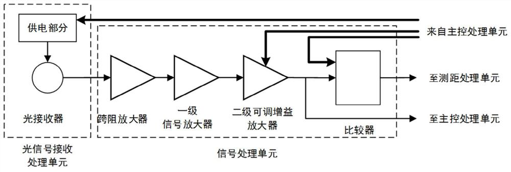
[0045]This embodiment provides an optical signal receiving processing device for a laser radar system, such asfigure 2 Indicated. The principle is similar to that of the embodiment. The present embodiment is a solution combined with a circuit structure and a control logic. Specifically include: sequentially connected light receiver, cross-resistance amplifier, primary signal amplifier, secondary adjustable gain amplifier, adjustable threshold comparator; where the light receiver can respond to the power supply voltage control signal from the main control unit, realize itself Power supply voltage adjustment; secondary adjustable gain amplifier can respond to gain adjustment signals from the main control unit; the adjustable threshold comparator enables threshold adjustment in response to the threshold adjustment signal from the main control unit.

[0046]That is, the present embodiment is intended to provide a circuit structure for receiving and processing optical signals, making the fi...

Embodiment approach 3

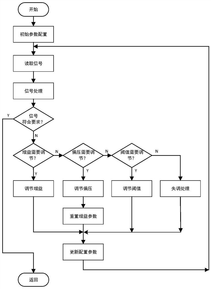
[0050]The present embodiment provides an optical signal receiving processing method of a laser radar system, which is based on the reception processing apparatus of the second embodiment, such asimage 3As shown, including: Depending on the amplitude, signal repetition frequency, and signal arrival time to determine whether the output of the secondary adjustable gain amplifier meets the preset requirements. If it does not meet, the zoom in the secondary adjustable gain amplifier is adjusted. The gain, the power supply voltage of the light receiver and the threshold voltage of the adjustable threshold comparator until the processed signal meets the preset requirements.

[0051]

[0052]This embodiment includes a laser radar system, such asfigure 1 As shown, an optical signal transmitting unit, a light signal receiving unit, a signal processing unit, a ranging processing unit, a master processing unit, a data communication unit, and a MEMS spray mirror, and a drive module.

[0053]The design us...


PUM

PropertyMeasurementUnit
Gainaaaaaaaaaa

Abstract

The invention relates to a laser radar system, belongs to the field of laser radar and laser ranging, and aims to overcome the defects of weak signal, high frequency and complex background noise in a complex environment in the prior art. The laser radar system comprises an optical signal transmitting unit, an optical signal receiving and processing unit, a distance measurement processing unit and a main control processing unit; the main control unit is used for generating a laser trigger pulse signal to the optical signal transmitting unit; the optical signal receiving and processing unit comprises an optical receiver, a trans-impedance amplifier, a primary signal amplifier, a secondary adjustable gain amplifier and an adjustable threshold comparator which are connected in sequence; and the main control processing unit can adjust the power supply voltage of the optical receiver, the amplification gain of the secondary adjustable gain amplifier and the threshold voltage of the adjustable threshold comparator according to the output result of the secondary adjustable gain amplifier. The invention further comprises an optical signal receiving and processing device and an optical signal receiving and processing method. One application of the invention is a laser radar system design.

Description

Technical field[0001]The present invention relates to the field of laser radar and laser ranging, and more particularly to a laser radar system, an optical signal receiving processing apparatus, and an optical signal receiving process.Background technique[0002]The function of laser radar implementation is to measure target distance and location, applied to precise measurement, target positioning, automatic driving. The laser radar has a multi-line scanning method and a MEMS spray-based scan, which is common in a manner in which the measuring method is used in the use of light flight, which is common, which is calculated by measuring the time difference of light transmission and reception. Distance.[0003]Based on MEMS spray mirror, there is a small size and low cost, and is the main direction of future design development of laser radar. The laser radar system is affected by environmental factors, and the optical signal in the external environment has a great impact on laser radar mea...

Claims


Application Information

Patent Timeline
IPC IPC(8): G01S7/487
CPCG01S7/4873
Inventor 王福王永法马微
Owner 哈尔滨新光光电科技股份有限公司
Why Eureka
Try Eureka