Laser pulse welding method for thin-wall aluminum alloy butt joint

A laser pulse and butt joint technology, which is applied in laser welding equipment, welding equipment, metal processing equipment, etc., can solve complex structure products that cannot be welded, increase equipment cost and process complexity, difficult single-sided welding and double-sided forming, etc. problems, to achieve the effect of improving the problem of porosity defects, avoiding porosity defects, and small fluctuations in penetration depth

Pending Publication Date: 2021-04-30
BEIJING HANGXING MACHINERY MFG CO LTD
View PDF12 Cites 6 Cited by
  • Summary
  • Abstract
  • Description
  • Claims
  • Application Information

AI Technical Summary

Problems solved by technology

When laser welding with the above methods, due to the small thickness of the product, the problem of unstable weld formation is likely to occur during welding, either incomplete penetration or weld leakage, and it is difficult to achieve single-sided welding and double-sided forming
[0005] Chinese patent CN 109759699 A discloses a laser welding process for 5083 aluminum alloys. This method uses laser pulses as a heat source and realizes the welding of thin-walled 5083 aluminum alloys in a swinging manner. The operation is complicated and requires a preheating device. On the one hand, it increases The cost of equipment and the complexity of the process are reduced, and it can only meet the needs of simple flat plate welding, and it cannot be welded for products with complex structures such as cavities.

Method used


Image

  • Laser pulse welding method for thin-wall aluminum alloy butt joint
  • Laser pulse welding method for thin-wall aluminum alloy butt joint
  • Laser pulse welding method for thin-wall aluminum alloy butt joint

Examples


Embodiment 1

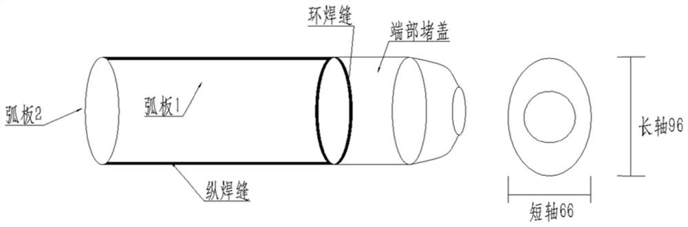
[0041] The present invention is implemented on a certain type of underwater buoyancy cavity structure. The cavity shape is a slender structure with a length of 1648 mm, an elliptical cross-section, a major axis of the ellipse of 96 mm, and a minor axis of the ellipse of 66 mm. The elliptical cavity is composed of two arc plates separated from the plane where the long axis is located and two end caps. The joint to be welded is a butt structure with a thickness of 1mm. The material is 5A06 aluminum alloy. The structure of the underwater buoyancy cavity is as follows figure 1 shown. The specific method is as follows:

[0042] Pickling before welding: pickling the 5A06 aluminum alloy parts, degreasing, and drying;

[0043] Cleaning before welding: clean the parts that have been processed to dimensional accuracy, use laser to clean the parts to be welded, the average laser power is 200W, the pulse frequency is 100Hz, the width of the parts to be welded is not less than 15mm, polis...


PUM


Abstract

The invention provides a laser pulse welding method for a thin-wall aluminum alloy butt joint. The laser pulse welding method includes the steps that step 1, 5A06 aluminum alloy parts are subjected to acid pickling and oil stain removal; step 2, to-be-welded parts of the parts which are processed to reach the size precision is cleaned; step 3, the to-be-welded parts are assembled together in a butt joint mode through a positioning clamp, and the to-be-welded parts are clamped to a rotating device of a laser welding machine; step 4, a cavity is filled with back protection gas, and gas protection is conducted on the back face of a weld joint; step 5, a laser angle and a shielding gas direction and flow are adjusted, laser pulse welding process parameters are set, and a weld joint track is determined for laser welding; and step 6, after a tool is disassembled, the forming quality of the front and back surfaces of the weld joint is checked, and a surface oxide layer of the weld joint is polished. According to the laser pulse welding method for the thin-wall aluminum alloy butt joint, the butt welding of the thin-wall aluminum alloy can be achieved under appropriate technological parameters, a large heat affected zone and air holes generated during laser welding are avoided, the strength of the obtained butt welding joint is high, and the cavity has good pressure resistance.

Description

technical field [0001] The invention belongs to the field of welding technology, in particular to a laser pulse welding method for a thin-walled aluminum alloy butt joint. Background technique [0002] 5A06 aluminum alloy is a non-heat treatment strengthened aluminum alloy, which is a typical alloy of the Al-Mg system. Due to its high strength, small specific gravity and good corrosion resistance, it has been widely used in aerospace, transportation and other fields. [0003] A certain type of underwater buoyancy cavity structure uses 5A06 as the raw material, and the design structure of the cylinder is as follows figure 1 , consisting of two arc plates and two end caps, the product is lightweight, the wall thickness is 1mm, the weld seam does not need to be processed to lock the bottom, and it is required to be welded on one side and formed on both sides. [0004] Chinese patent CN 107442935 A discloses a laser swing welding process for aluminum alloys. In this method, a ...

Claims


Application Information

Patent Timeline
Patent Type & Authority Applications(China)
IPC IPC(8): B23K26/21B23K26/14B23K26/60B23K26/70
CPCB23K26/21B23K26/14B23K26/60B23K26/702
Inventor 王毅王志敏孙少波步贤政任金欣谈哲君李天翔
Owner BEIJING HANGXING MACHINERY MFG CO LTD
Why Eureka
Try Eureka