
Combined machining method suitable for threaded hole of hard alloy cutter bar

A cemented carbide knife and composite machining technology, which is used in metal processing equipment, manufacturing tools, laser welding equipment, etc., can solve the problem of difficulty in ensuring the size and accuracy of the internal thread of cemented carbide tool bars, low processing efficiency, non-uniform shrinkage, etc. question

Active Publication Date: 2021-05-07
HEFEI UNIV OF TECH +1
View PDF8 Cites 1 Cited by
  • Summary
  • Abstract
  • Description
  • Claims
  • Application Information

AI Technical Summary

Problems solved by technology

[0003] Since the installation of the superhard material blade needs to be fixed by opening a threaded hole on the carbide shank, the processing of the internal thread of the tungsten carbide shank has always been a technical problem. The traditional internal thread processing methods include tapping and cold extrusion. Forming and milling, but for the carbide tool holder due to its high hardness and small thread hole diameter, it is difficult to use the traditional internal thread processing method normally
Although the inner thread of the cemented carbide tool holder can be formed by special molding, because the compact is still fired, it will eventually produce non-uniform shrinkage, and it is difficult to ensure the size and accuracy of the inner thread of the carbide tool holder after shrinkage. Therefore, The processing of the internal thread of the carbide tool holder can only be completed by subsequent processing
[0004] EDM internal thread is generally realized through the rotation and translation of the spindle with electrodes, mainly through axial helical screwing, the processing efficiency is low during the processing, and the electrode loss will also affect the machining accuracy of the internal thread

Method used


Image

  • Combined machining method suitable for threaded hole of hard alloy cutter bar
  • Combined machining method suitable for threaded hole of hard alloy cutter bar
  • Combined machining method suitable for threaded hole of hard alloy cutter bar

Examples


Embodiment Construction

[0027] The embodiments of the present invention are described in detail below. This embodiment is implemented on the premise of the technical solution of the present invention, and detailed implementation methods and specific operating procedures are provided, but the protection scope of the present invention is not limited to the following implementation example.

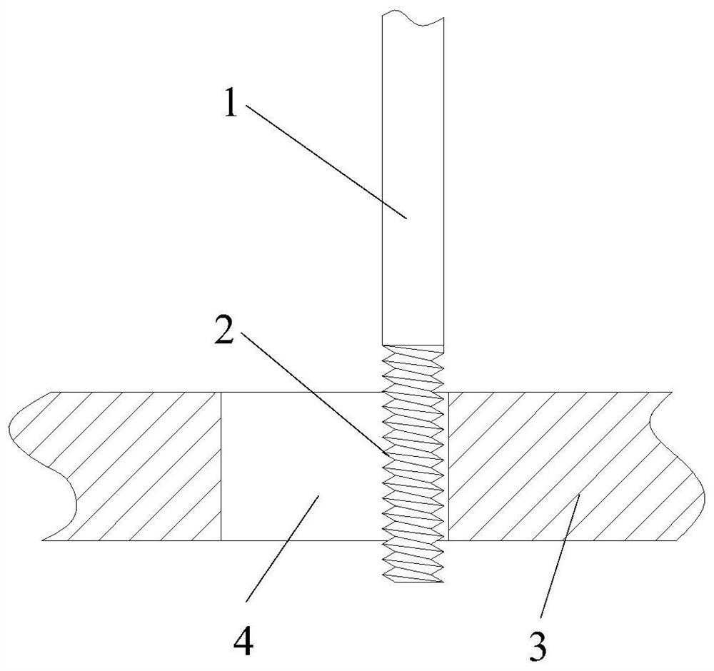
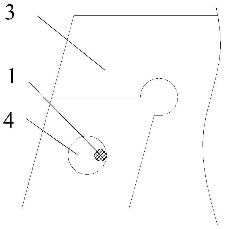
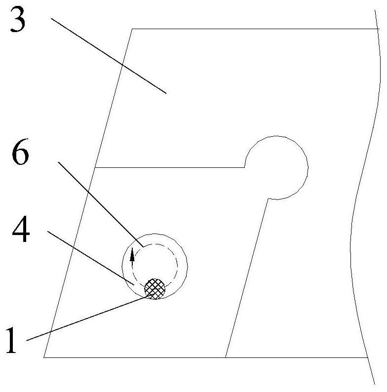
[0028] see Figure 1 to Figure 4 , this embodiment discloses a composite processing method suitable for threaded holes of cemented carbide tool rods, the composite processing method is carried out in sequence according to the following steps:

[0029] Step 1. Process the threaded bottom hole 4 on the cemented carbide shank 3 by means of laser or electric discharge machining. The threaded bottom hole 4 is a circular smooth hole that penetrates up and down; because both laser cutting and electric spark can realize superhard High-efficiency machining of materials, a circular smooth hole is machined on the cemented ca...


PUM


Abstract

The invention discloses a combined machining method suitable for a threaded hole of a hard alloy cutter bar. The combined machining method sequentially comprises the following steps that 1, a threaded bottom hole is machined in the hard alloy cutter bar in a laser or electric spark machining manner; 2, an external thread is machined on the copper rod as an electrode; and 3, the electrode is installed on a main shaft of an electric spark forming machine tool, the hard alloy cutter bar is installed on a workbench of the electric spark forming machine tool, the electrode is driven by the main shaft to horizontally move in a horizontal plane formed by an X axis and a Y axis, an internal thread is machined in an electric spark machining manner, and a horizontal movement track is a circle concentric with the thread bottom hole. Compared with the prior art, the combined machining method has the advantages that the machining efficiency and machining precision of the threaded hole of the hard alloy cutter bar can be guaranteed, threaded hole machining size errors caused by electrode loss can be avoided, and threaded holes of various diameters can be machined only through one electrode.

Description

technical field [0001] The invention relates to the technical field of processing cemented carbide materials, in particular to a compound processing method suitable for threaded holes of cemented carbide tool rods. Background technique [0002] In recent years, with the development of the machinery industry, the application requirements of high-hardness materials have become more and more extensive, and more and more challenges have been raised for its processing technology. For the field of metal cutting, cemented carbide materials are due to their high Hardness, strength and wear resistance, so that it can be used not only on knives, but also on the tool holder of superhard tools, such as diamond tools or cubic boron nitride tools. The hardness of the tool itself is extremely high. In order to further reduce the Vibration, carbide material becomes the ideal choice for the tool holder. [0003] Since the installation of the superhard material blade needs to be fixed by ope...

Claims


Application Information

Patent Timeline
IPC IPC(8): B23H9/00B23H9/14B23K26/382
CPCB23H9/003B23H9/14B23K26/382
Inventor 杨海东陆贤宇张俊生鲁晶张国富郑学云张理宝商永森夏锡全
Owner HEFEI UNIV OF TECH
Learn More