
Biomass gas-carbon co-production rotary gasification furnace

A technology of biomass gas and gasifier, applied in the direction of gasification process, biofuel, coke oven, etc., can solve the problem of energy-saving and environmental protection production concept of renewable energy production line, lack of uniform internal gas treatment, production line process completion time Lengthening and other problems, to achieve the effect of reducing gas homogenization process, high gas homogenization performance, and shortening production hours

Inactive Publication Date: 2021-05-11
永安千禾生物能源有限公司
View PDF5 Cites 0 Cited by
  • Summary
  • Abstract
  • Description
  • Claims
  • Application Information

AI Technical Summary

Problems solved by technology

[0003] In the production line used for the co-production of biomass environmental protection fuel gas and charcoal, gasification furnaces are usually used to gasify the gas products of fuel combustion. The function of uniform treatment has certain production drawbacks, and it is necessary to increase the production process. The operation through the connected homogenization equipment increases the production cost to a certain extent, and the overall process completion time of the production line becomes longer, and the energy consumption increases, which is not in line with modern Energy saving and environmental protection production concept of automated renewable energy production line

Method used


Image

  • Biomass gas-carbon co-production rotary gasification furnace
  • Biomass gas-carbon co-production rotary gasification furnace
  • Biomass gas-carbon co-production rotary gasification furnace

Examples


Embodiment Construction

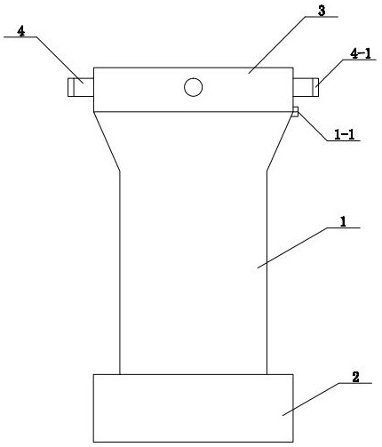
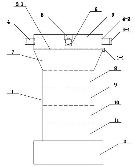
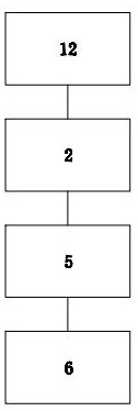
[0019] see Figure 1-Figure 3 As shown, the technical solution adopted in this specific embodiment is: it includes a gas-carbon cogeneration furnace body 1, a control base 2, an upper cover body 3, an air outlet pipe 4, a motor 5, a propeller 6, a drying chamber 7, and a pyrolysis chamber 8 , oxidation bin 9, reduction bin 10, ash outlet bin 11, control computer 12; hinge 1-1, sealing ring 3-1, connection nozzle 4-1, flue gas filter screen 4-2; described carbon cogeneration The lower part of the furnace body 1 is provided with a control base 2, and the carbon cogeneration furnace body 1 is fixed on the control base 2, and the upper cover body 3 is installed on the upper part of the carbon cogeneration furnace body 1, and the upper cover body 3 is provided with a gas outlet pipe at the front, rear, left, and right sides 4. A motor 5 is installed above the inside of the upper cover body 3, and a propeller 6 is rotated and connected to the bottom of the motor 5; the interior of t...


PUM


Abstract

The invention discloses a biomass gas-carbon co-production rotary gasification furnace, and relates to the technical field of renewable energy source production. The biomass gas-carbon co-production rotary gasification furnace comprises a gas-carbon co-production furnace body, a control base, an upper cover body, a gas outlet pipeline, a motor, a propeller, a drying bin, a pyrolysis bin, an oxidation bin, a reduction bin, an ash discharge bin and a control computer, and the control base is arranged on the lower portion of the charcoal co-production furnace body, the charcoal co-production furnace body is fixed to the control base, the upper cover body is installed on the upper portion of the charcoal co-production furnace body, the front, the rear, the left and the right of the upper cover body are each provided with an air outlet pipeline, the motor is arranged on the upper portion in the upper cover body, and the propeller is rotationally connected to the lower portion of the motor. A rotary gas homogenizing device is installed, the high gas homogenizing performance is achieved, the working efficiency is high, gas products generated by renewable fuel can be homogenized and then conveyed to external gas equipment, additional gas homogenizing procedures are reduced, additional equipment does not need to be added, the production cost is reduced, and meanwhile normal gas conveying is guaranteed.

Description

technical field [0001] The invention relates to the technical field of renewable energy production, in particular to a rotary gasifier for combined production of biomass gas and charcoal. Background technique [0002] Biomass fuel: refers to the burning of biomass materials as fuel, generally mainly agricultural and forestry wastes (such as straw, sawdust, bagasse, rice bran, etc.). The main difference is from fossil fuels. In the current national policy and environmental protection standards, direct combustion of biomass is a highly polluting fuel, which is only used in large stoves in rural areas and is not allowed to be used in cities. The application of biomass fuel is actually mainly biomass briquette fuel, which uses agricultural and forestry waste as raw materials, and is made into various shapes (such as lumps, granules, etc.) through crushing, mixing, extrusion, drying and other processes. A new type of clean fuel that can be directly burned. Biomass energy refer...

Claims


Application Information

Patent Timeline
Patent Type & Authority Applications(China)
IPC IPC(8): C10J3/64C10J3/20C10J3/62C10J3/72C10J3/84C10B53/02C10B57/10
CPCC10J3/64C10J3/20C10J3/62C10J3/723C10J3/84C10J3/725C10B53/02C10B57/10C10J2300/0909C10J2300/0916C10J2300/0956Y02E50/10Y02P20/133
Inventor 周建华吴振华魏振春林海青石俊雄何少伟林菁俤陈国炘张瑞芬
Owner 永安千禾生物能源有限公司
Learn More