Pressure porous valve chip and detection method thereof

A technology of pressure valve and orifice valve, which is applied in the field of medical equipment and can solve problems such as difficult operation

Active Publication Date: 2021-05-18
YANGZHOU UNIV
View PDF15 Cites 3 Cited by
  • Summary
  • Abstract
  • Description
  • Claims
  • Application Information

AI Technical Summary

Problems solved by technology

[0004] The purpose of the present invention is to overcome the deficiencies in the prior art and provide a pressure porous valve chip, which solves the technical problem of difficult operation in the prior art. The present invention has simple structure, convenient operation and high flexibility

Method used


Image

  • Pressure porous valve chip and detection method thereof
  • Pressure porous valve chip and detection method thereof
  • Pressure porous valve chip and detection method thereof

Examples


Embodiment 2

[0052] The method for detecting the chip in embodiment 1 comprises the following steps:

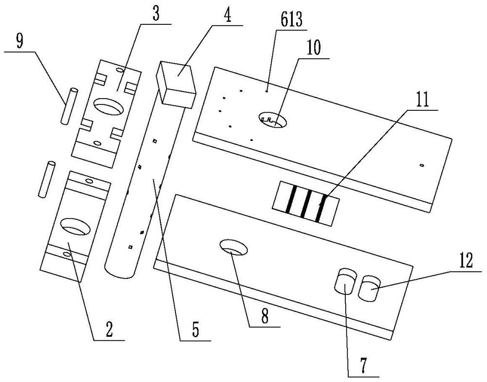
[0053] (1) Add samples to the corresponding liquid storage tanks through each liquid inlet hole 612, put the chip into the supporting detection equipment, the peristaltic pump 14 works, and the samples in the liquid storage tank one 605 are driven by the peristaltic pump 14, Pass through the microfluidic branch channel 613, the fluid through hole 1 509, the flow area 601, and the microfluidic main channel 1 602 to enter the branch reaction channel 611. When the sample starts to enter the buffer tank 7, the peristaltic pump 14 stops and stops for 15 minutes , block the vacant sites of the three capture antibody bands on the antigen-antibody pattern sheet 11 to prevent non-specific adsorption. After 15 minutes of blocking, the peristaltic pump 14 pneumatically sucks out the sample and enters the waste liquid tank 12 or the buffer tank 7. The peristaltic pump 14 stop action;

[0054] (2) Af...

Embodiment 3

[0068] Perform linear detection on the three tumor marker standard products in Example 2, pre-coat 40 μg / mL of AFP capture antibody on the exposed antigen-antibody pattern sheet 11 before detection, use PBS buffer (PH=7.4) as dilution solution, the concentration of AFP standard is 0ng / mL, 5ng / mL, 10ng / mL, 20ng / mL, 40ng / mL, 80ng / mL, 160ng / mL, 320ng / mL, take 30μL and add it to storage tank 2 606 ; Add the 50ug / mL biotin-labeled AFP antibody solution of 30ul in reservoir five; All the other detection steps are the same as in Example 2, and each standard product is measured 3 times with 3 microfluidic chips respectively, and the quantitative analysis system is based on The ratio between the AFP concentration and the gray value of chemiluminescence was fitted to calculate the average value of 8 different concentrations, and a standard curve was drawn.

[0069] Pre-coat the exposed antigen-antibody pattern sheet 11 with 50 μg / mL of CEA capture antibody, use PBS buffer (PH=7.4) as th...

Embodiment 4

[0073] Add the mixed standard sample of AFP and CEA into the liquid storage tank 2 606; add the detection antibody corresponding to the standard in the liquid storage tank 5 609, and the remaining detection steps are the same as in Example 2, and the exposure time of the chemiluminescence instrument is 30s ,get Figure 13-1 image.

[0074] Add the mixed standard sample of CEA and TSGF into the liquid storage tank 2 606; add the detection antibody corresponding to the standard in the liquid storage tank 5, and the remaining detection steps are the same as in Example 2, and the exposure time of the chemiluminescence instrument is 30s. get Figure 13-2 image.

[0075] The mixed standard sample of AFP and TSGF was added to the second storage tank 606; the detection antibody corresponding to the standard was added to the fifth storage tank 609, and the rest of the detection steps were the same as in Example 2. The exposure time of the chemiluminescence instrument was 30s, and ...


PUM

PropertyMeasurementUnit
linear rangeaaaaaaaaaa

Abstract

The invention discloses a pressure porous valve chip and a detection method thereof and belongs to the technical field of medical instruments. The pressure porous valve chip comprises a substrate sheet and a pressure valve body; a channel sheet is tightly attached to the upper side of the substrate sheet; a plurality of microfluid branch channels communicated with upper mounting holes are distributed at the downward end of the channel sheet; liquid storage grooves are formed in the channel sheet at the ends, away from the upper mounting holes, of the microfluid branch channels; a plurality of liquid inlet holes in one-to-one correspondence with the liquid storage grooves are formed in the channel sheet;the pressure valve body is connected with the channel sheet and the substrate sheet;and a plurality of fluid through holes in one-to-one correspondence with the microfluid branch channels are formed in the height direction of the pressure valve body; the fluid through holes can cover the areas where the corresponding microfluid branch channels are located; the downward end of the channel sheet is provided with a circulation area, a first microfluid main channel communicated with the circulation area and a negative pressure connector; one end of the circulation area is communicated with the other ends of the fluid through holes; and the other end of the circulation area is communicated with the negative pressure connector through the first microfluid main channel. The pressure porous valve chip is convenient to operate and high in flexibility.

Description

technical field [0001] The invention belongs to the technical field of medical devices, in particular to a pressure porous valve chip. Background technique [0002] In vitro diagnosis refers to the method of detecting human blood, body fluid and other samples outside the human body, and then diagnosing body functions or disease information. In vitro diagnostic products can quickly and accurately diagnose diseases in the early stage, and provide effective technical support for disease prevention and prognosis assessment. The development of highly automated, integrated and miniaturized diagnostic equipment has become the main component of the in vitro diagnostic market. [0003] At present, the immunodiagnosis in most hospitals and laboratories uses enzyme-labeled plates or centrifuge tubes as reaction vessels, and is equipped with large-scale detection instruments. Although this method has high stability and good repeatability, it requires a large amount of reagents, high de...

Claims


Application Information

Patent Timeline
Patent Type & Authority Applications(China)
IPC IPC(8): B01L3/00G01N21/76
CPCB01L3/502738B01L3/50273B01L3/5027G01N21/76B01L2200/0636B01L2200/0642B01L2200/0694B01L2300/049B01L2300/14B01L2400/0475B01L2400/0622B01L2400/06
Inventor 尹彬沣钱长成
Owner YANGZHOU UNIV
Why Eureka
Try Eureka