Coupling counteracting path branch knot and high-isolation millimeter wave phased array antenna based on coupling counteracting path branch knot
A phased array antenna and coupling path technology, applied in the directions of antenna, antenna coupling, resonant antenna, etc., can solve the problems of cross section, complex design, unsuitable for antenna design, etc., achieve easy processing, realize broadband matching characteristics, cost and weight small effect
- Summary
- Abstract
- Description
- Claims
- Application Information
AI Technical Summary
Problems solved by technology
Method used
Image
Examples
Embodiment 1
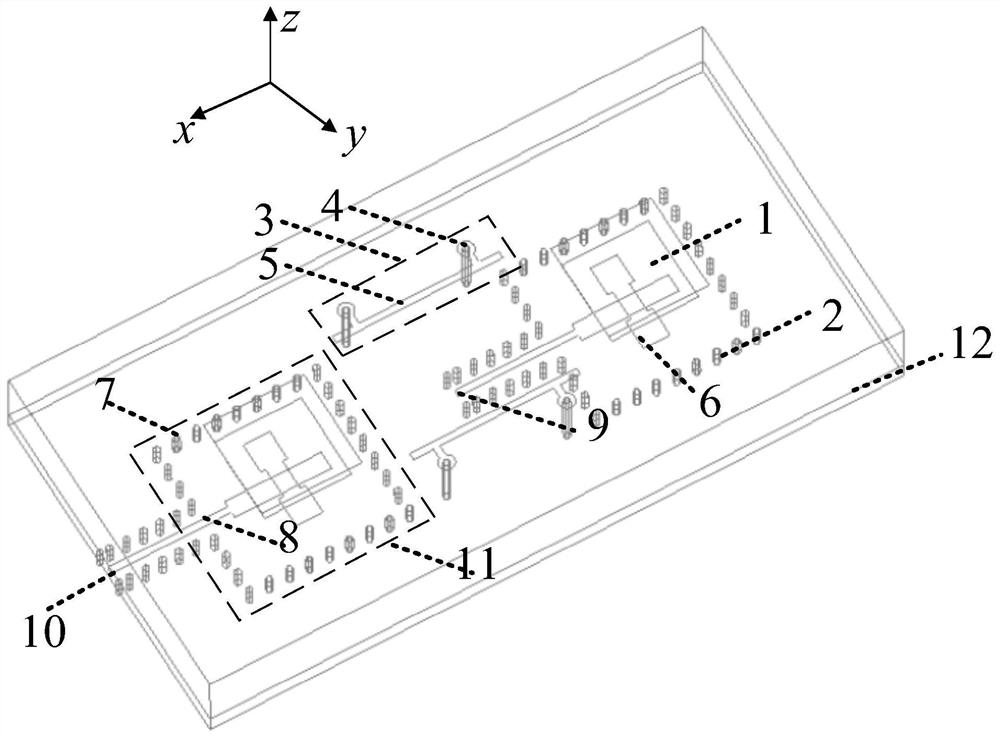
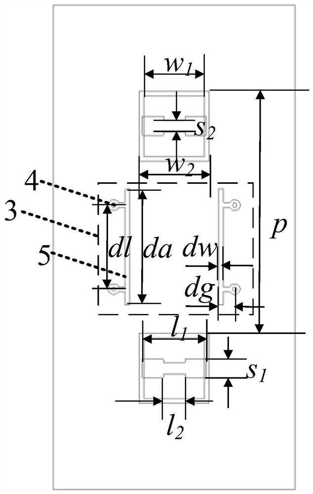
[0056] In this embodiment, the coupling cancellation path stub 3 includes a pair of first grounding posts 4 and a π-shaped metal strip 5 .
[0057] In this example, if Figure 1a and Figure 1b As shown, the high-isolation millimeter-wave phased array antenna includes two radiating laminated microstrip antenna units 1 and two coupling-cancellation path stubs 3, forming a high-isolation millimeter-wave binary antenna array based on the coupling-cancellation path.
[0058] In a high-isolation millimeter-wave binary antenna array based on a coupling cancellation path, two radiating stacked microstrip antenna units 1 are respectively provided with a first port 9 and a second port 10, and the first port 9 and the second port 10 are respectively located at On the center line of the corresponding radiating stacked microstrip antenna unit 1; the first port 9 is excited, and the energy of the feed network layer 11 is coupled to the radiating stacked microstrip antenna unit 1 through th...
Embodiment 2
[0071] In this embodiment, the coupling cancellation path stub 3 includes two pairs of first ground pillars 4 and two π-shaped metal strips 5 .
[0072] In this example, if Figure 6a and Figure 6b As shown, the high-isolation millimeter-wave phased array antenna includes two radiating laminated microstrip antenna units 1 and two coupling-cancellation path stubs 3, forming a high-isolation millimeter-wave binary antenna array based on the coupling-cancellation path.
[0073] In a high-isolation millimeter-wave binary antenna array based on a coupling cancellation path, two radiating stacked microstrip antenna units 1 are respectively provided with a first port 9 and a second port 10, and the first port 9 and the second port 10 are respectively located at On the center line of the corresponding radiating stacked microstrip antenna unit 1; the first port 9 is excited, and the energy of the feed network layer 11 is coupled to the radiating stacked microstrip antenna unit 1 thro...
Embodiment 3
[0086] In this embodiment, the coupling cancellation path stub 3 includes a pair of first grounding posts 4 and a π-shaped metal strip 5 .
[0087] In this example, if Figure 11a and Figure 11b As shown, the high-isolation millimeter-wave phased array antenna includes four identical subarrays, and the entire array is provided with four subarray ports: the first port 9, the second port 10, the third port 12, and the fourth port 13, such as Figure 12a As shown, the first port 9, the second port 10, the third port 12, and the fourth port 13 are placed under the sub-array, arranged in a row at a distance of 5mm, which is convenient for testing, and each sub-array includes four radiating stacked microstrip antennas Unit 1 and three feed network layers 11. The feed network layer 11 is a feed network of a one-to-two substrate integrated waveguide power divider; the sub-array includes a radiating laminated microstrip antenna unit 1 and a second grounding post 7 The shielding meta...
PUM
 Abstract
Description
Claims
Application Information
 - R&D
- Intellectual Property
- Life Sciences
- Materials
- Tech Scout
- Unparalleled Data Quality
- Higher Quality Content
- 60% Fewer Hallucinations
Browse by: Latest US Patents, China's latest patents, Technical Efficacy Thesaurus, Application Domain, Technology Topic, Popular Technical Reports.
© 2025 PatSnap. All rights reserved.Legal|Privacy policy|Modern Slavery Act Transparency Statement|Sitemap|About US| Contact US: help@patsnap.com


