Selective relay protection configuration method

A technology of relay protection and configuration method, which is applied in the direction of emergency protection circuit devices, circuit devices, electrical components, etc., which can solve the difficulties in project implementation, failure to ensure fault removal of relay protection, and energy storage power stations that cannot meet the peak regulation and frequency regulation of the power grid , black start and other application requirements, to achieve the effect of guaranteeing normal operation and guaranteeing selectivity

Pending Publication Date: 2021-05-28
ZHEJIANG ZHENENG ELECTRIC POWER CO LTD XIAOSHAN POWER PLANT +3
View PDF0 Cites 0 Cited by
  • Summary
  • Abstract
  • Description
  • Claims
  • Application Information

AI Technical Summary

Problems solved by technology

With the large-scale construction and operation of large-scale energy storage power stations, the main wiring structure and relay protection of the original energy storage power stations cannot meet the existing needs. When a fault occurs, the relay protection cannot be guaranteed to selectively remove the fault. The energy storage power station cannot meet the application requirements of the power grid such as peak regulation, frequency regulation, and black start
It is necessary to clarify how to dynamically determine the fixed value of the braking current. Since there are multiple windings on the low-voltage side, the magnitude and phase of each current are different, intertwined with problems such as excitation inrush current, which has caused great difficulties in project implementation.

Method used


Image

  • Selective relay protection configuration method
  • Selective relay protection configuration method
  • Selective relay protection configuration method

Examples


Embodiment Construction

[0023] The technical solutions of the present invention will be further described below in conjunction with the embodiments.

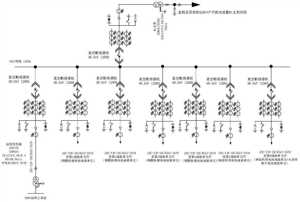
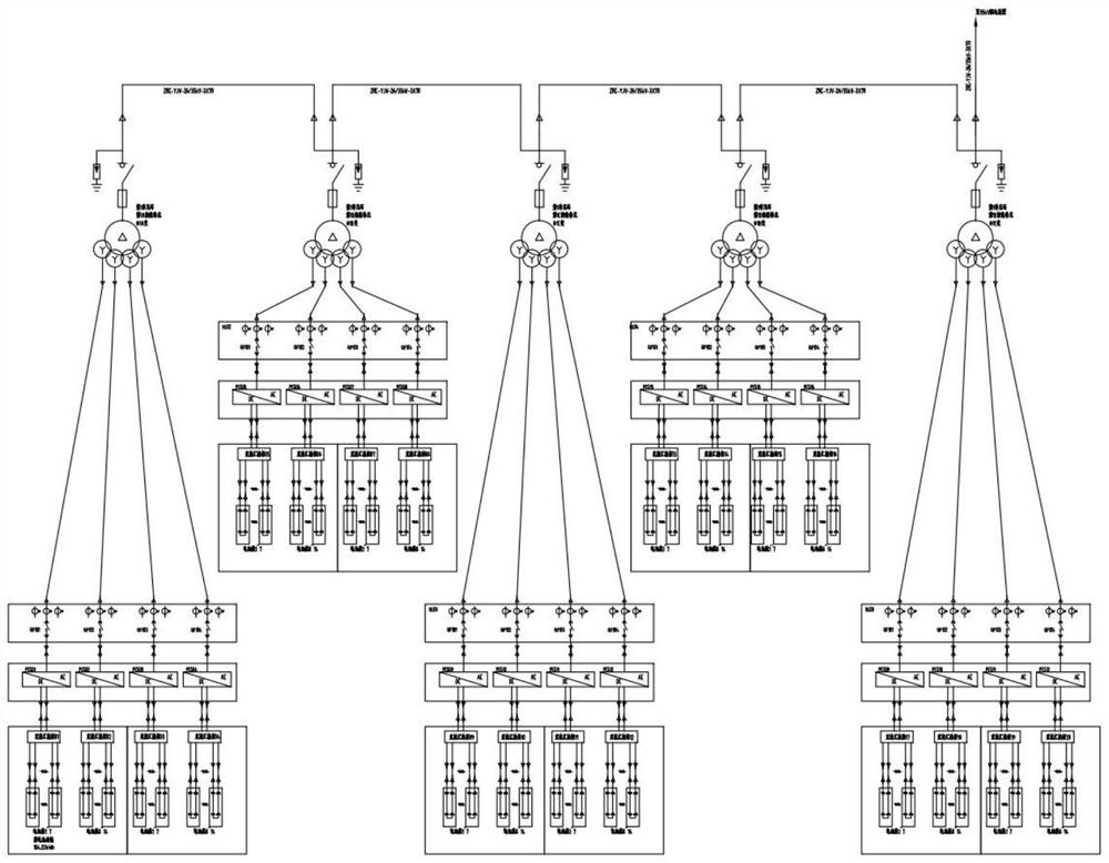
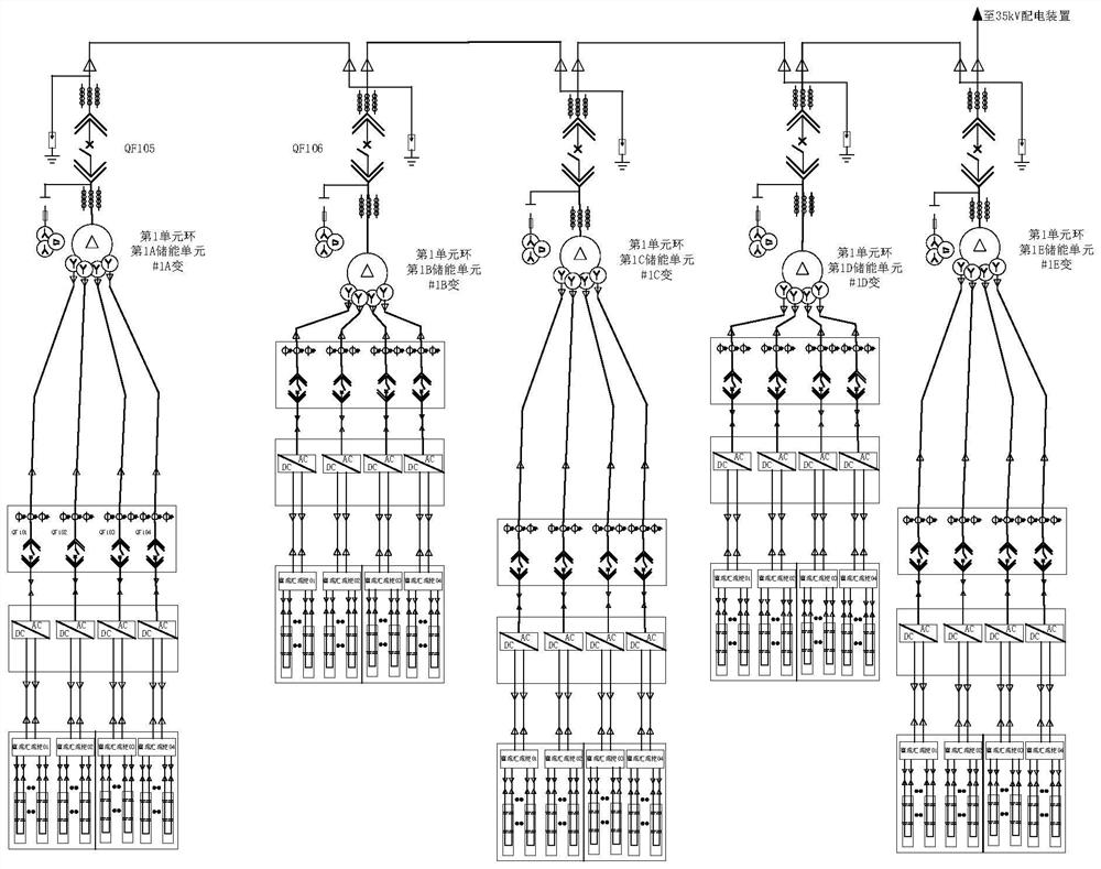
[0024] figure 1 It is a schematic diagram of a typical main wiring structure of a large-scale energy storage power station, and the exchange power of each energy storage unit ring is collected by the busbar; figure 2 It is a schematic diagram of the main wiring structure of a typical energy storage unit ring in a large-scale energy storage power station, and the exchange power of five identical energy storage units is collected by the busbar. Among them, a fuse combined with an isolating switch is used above the multi-winding bus transformer of a single energy storage unit. However, the fuse needs to be fused only when the fault current reaches a large value, and the inverter power supply cannot withstand a large Fault current, usually blocked automatically after a line fault, cannot provide continuous steady-state fault current to the fault point. ...


PUM


Abstract

The invention discloses a selective relay protection configuration method, wherein a braking constant value is set according to a comprehensive harmonic proportion, and a dynamic fuzzy control method is adopted to control a plurality of injection currents on the low-voltage side of a multi-winding conflux transformer based on the characteristic that the harmonic proportion and current distortion are in positive correlation. According to the method, the fault of a multi-winding confluence transformer side in an energy storage unit ring can be effectively handled, so that the single energy storage unit is selectively tripped when the fault occurs on the multi-winding confluence transformer side in the energy storage unit ring, it is ensured that relay protection selectively acts when the fault occurs, operation of the energy storage power station is maintained to the maximum extent, and safe and reliable operation of the whole power system is ensured.

Description

technical field [0001] The invention relates to a relay protection configuration method, in particular to a selective relay protection configuration method. Background technique [0002] With the rapid development of the economy, industrial electricity consumption, commercial electricity consumption, and residential electricity consumption have all increased significantly. The peak load of daily electricity consumption has increased year by year. Supply gap. Along with economic development, it is also facing severe environmental protection pressure. In order to gradually reduce the proportion of traditional thermal power generation with large pollution, countries around the world are gradually increasing the proportion of renewable energy such as photovoltaic power generation and wind power generation. [0003] However, with the gradual increase in the proportion of renewable energy power generation, the intermittence and volatility of new energy power generation has also b...

Claims


Application Information

Patent Timeline
Patent Type & Authority Applications(China)
IPC IPC(8): H02H7/26H02J3/38H02J3/24H02J3/28
CPCH02H7/26H02J3/381H02J3/24H02J3/28H02J2300/20
Inventor 吕力行刘骅裘淮飞杨冬梅余良辉王智季永超邓化彬
Owner ZHEJIANG ZHENENG ELECTRIC POWER CO LTD XIAOSHAN POWER PLANT
Why Eureka
Try Eureka