
Power and cold air combined supply system driven by medium and low temperature heat source

A low-temperature heat source and air-conditioning technology, which is applied in refrigerators, refrigeration and liquefaction, household refrigeration devices, etc., can solve the problems of insufficient supply and demand of heat sources in coastal cities, ineffective use of cold energy, and marine environmental pollution, etc., to achieve cascade Utilization, good temperature matching, and the effect of combined cooling and electricity supply

Active Publication Date: 2021-06-01
SHANDONG UNIV
View PDF11 Cites 3 Cited by
  • Summary
  • Abstract
  • Description
  • Claims
  • Application Information

AI Technical Summary

Problems solved by technology

The heat sink of the Kalina circulation system mostly uses cooling water or LNG (liquefied natural gas) after heating treatment. When cooling water is used, due to the high temperature, the required flow rate is relatively large, resulting in high power consumption of the water pump; when using LNG , usually needs to be heated by seawater or industrial waste heat, and then used as the heat sink of the Karina cycle system. This treatment method, on the one hand, causes problems such as energy waste, marine environmental pollution, and insufficient supply and demand of heat sources in coastal cities. On the other hand, LNG A large amount of cold energy is released during vaporization, and this part of cold energy is often not effectively utilized

Method used


Image

  • Power and cold air combined supply system driven by medium and low temperature heat source

Examples


Embodiment Construction

[0030] The present invention will be further described below in conjunction with the accompanying drawings and embodiments.

[0031] It should be noted that the following detailed description is exemplary and intended to provide further explanation of the present invention. Unless defined otherwise, all technical and scientific terms used herein have the same meaning as commonly understood by one of ordinary skill in the art to which this invention belongs.

[0032] It should be noted that the terminology used here is only for describing specific embodiments, and is not intended to limit exemplary embodiments according to the present invention. As used herein, unless the context clearly dictates otherwise, the singular is intended to include the plural, and it should also be understood that when the terms "comprising" and / or "comprising" are used in this specification, they mean There are features, steps, operations, means, components and / or combinations thereof.

[0033] In...


PUM


Abstract

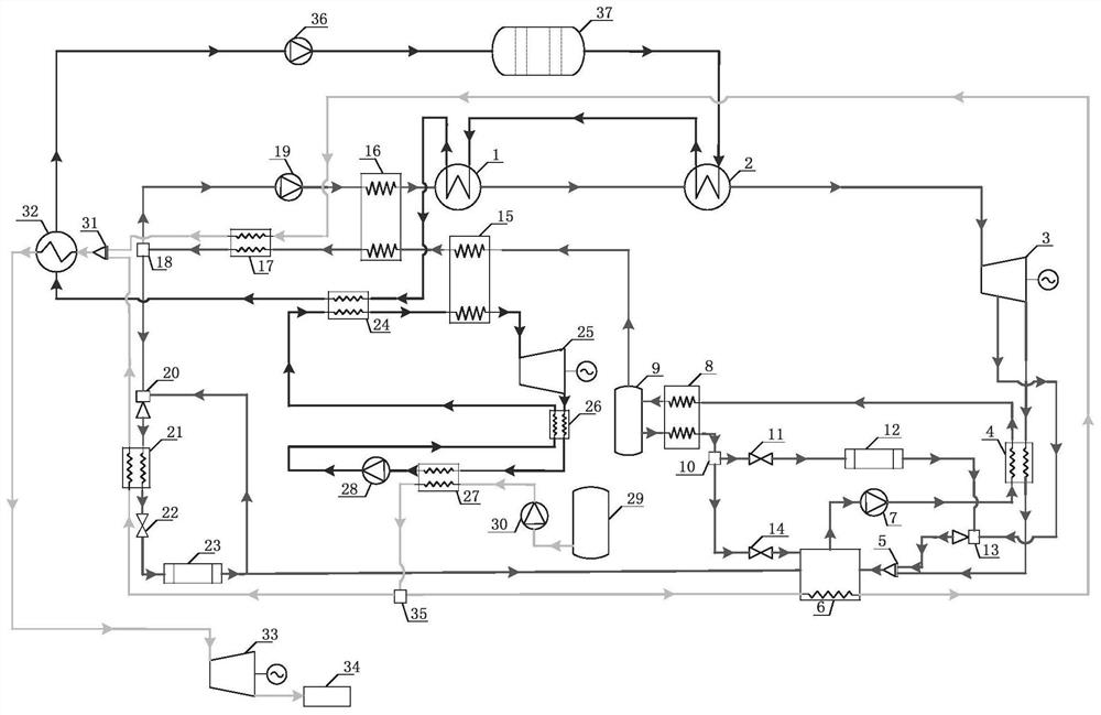
The invention discloses a power and cold air combined supply system driven by a medium and low temperature heat source. The power and cold air combined supply system comprises a medium and low temperature heat source circulation system, an LNG cold energy utilization circulation system, a Kalina circulation system, an organic Rankine circulation system, an external ejection type refrigeration circulation system and an internal ejection type refrigeration circulation system; the Kalina circulation system is coupled with the medium and low temperature heat source circulation system through a boiler and a superheater; the organic Rankine circulation system is coupled with the medium and low temperature heat source circulation system through an ORC preheater, and the organic Rankine circulation system is coupled with the Kalina circulation system through an ORC evaporator; an ejection flow of an ejector of the internal ejection type refrigeration circulation system is medium-high pressure ammonia gas led out from a certain position in the middle of a turbine in the Kalina circulation system, and the ejected flow is a two-phase flow of an outlet of a first evaporator; and an ejection flow of an ejector of the external ejection type refrigeration circulation system is ammonia water at an outlet of a condenser in the Kalina circulation system, and an ejected flow is a two-phase mixture at an outlet of an evaporator.

Description

technical field [0001] The invention belongs to the field of combined power, cold and air supply, and in particular relates to a combined power, cold and air supply system driven by a medium-low temperature heat source. Background technique [0002] The statements in this section merely provide background information related to the present invention and do not necessarily constitute prior art. [0003] With the progress of society, the consumption of non-renewable energy such as coal, oil, and natural gas is also increasing year by year, causing serious damage to the environment. In this case, it is particularly important to use heat source energy in stages to maximize energy utilization. It is one of the important ways to solve the current energy crisis and relieve environmental pressure. Medium and low temperature heat sources are relatively common in our lives and are one of the important components of heat sources, including solar energy, various waste heat from factori...

Claims


Application Information

Patent Timeline
Patent Type & Authority Applications(China)
IPC IPC(8): F25B9/08F25B15/04F25D3/10F01K25/10F01D15/10
CPCF01D15/10F01K25/10F25B9/08F25B15/04F25D3/10
Inventor 于泽庭梁文兴冯春雨
Owner SHANDONG UNIV
Learn More