Thermal cycle accurate temperature control gradient carbonization equipment and method for sludge treatment

A thermal cycle and equipment technology, applied in pyrolysis treatment of sludge, lighting and heating equipment, combustion methods, etc., can solve the problem of long-term operation stability of the drum carbonization furnace, and has not proposed the feasibility of sludge mixed with biomass, Lack of devices and methods for compounding biochar to achieve the effects of increasing calorific value, convenient maintenance, and thorough carbonization

Pending Publication Date: 2021-06-11
博仕燊环保科技(广州)有限公司
View PDF7 Cites 2 Cited by
  • Summary
  • Abstract
  • Description
  • Claims
  • Application Information

AI Technical Summary

Problems solved by technology

However, using these methods to treat and dispose of sludge, there are secondary pollution problems: ocean dumping and landfilling make the harmful substances contained in the sludge re-released; landfills occupy a large area; sludge incineration produces a large amount of toxic and harmful gases , a large demand for heat sources greatly increases the cost of sludge
Invention patents CN1112311532A, CN128119810510A, CN128111282A, CN1231138002A, etc. all describe the method of biomass carbonization to prepare biochar. Invention patent CN1111009885A discloses a device for drying and retorting sludge and garden waste, but there is still a lack of sludge blended with biomass for preparation The device and method of composite biochar have never proposed the feasibility of sludge blending with biomass in the actual operation process; utility models CN212911219U, CN2122109221U and invention patent CN111904339A all disclose a drum type (rotary kiln) sludge carbonization device, However, there are problems of long-term operation stability and leakage of odor and waste gas in the drum carbonization furnace.

Method used


Image

  • Thermal cycle accurate temperature control gradient carbonization equipment and method for sludge treatment
  • Thermal cycle accurate temperature control gradient carbonization equipment and method for sludge treatment
  • Thermal cycle accurate temperature control gradient carbonization equipment and method for sludge treatment

Examples


specific Embodiment approach

[0081] The present invention will be further described in detail below in conjunction with specific examples, but the embodiments of the present invention are not limited thereto, and for process parameters not specifically indicated, conventional techniques can be referred to.

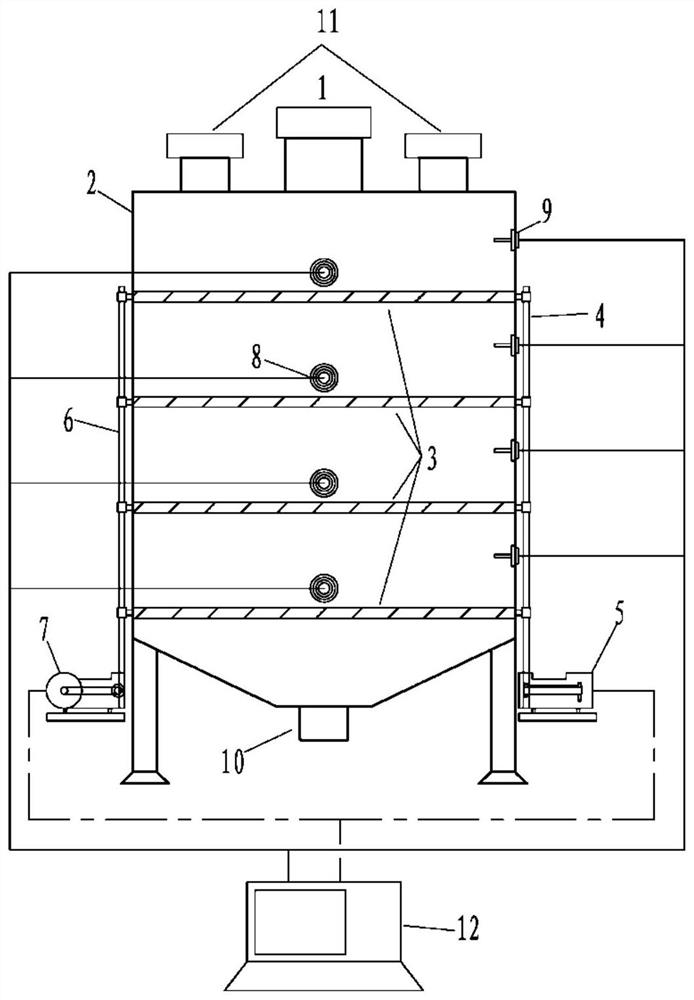
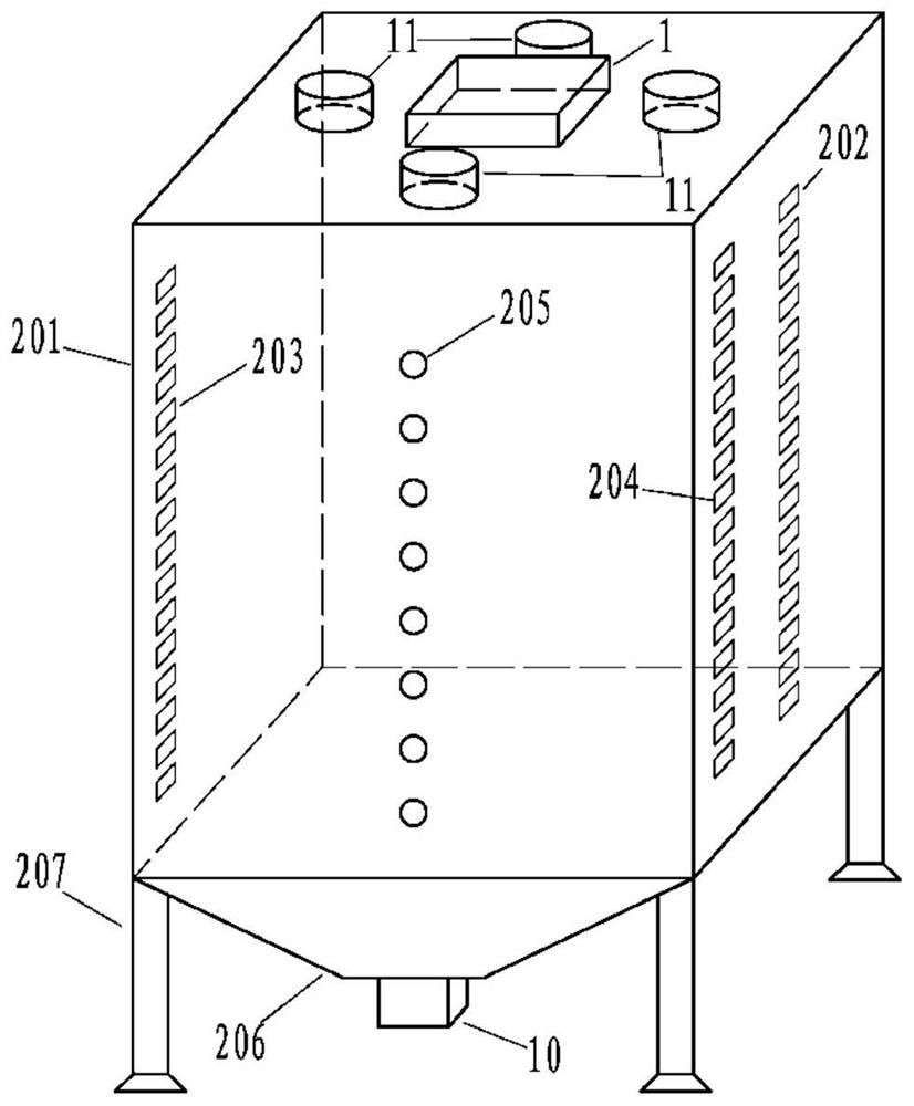
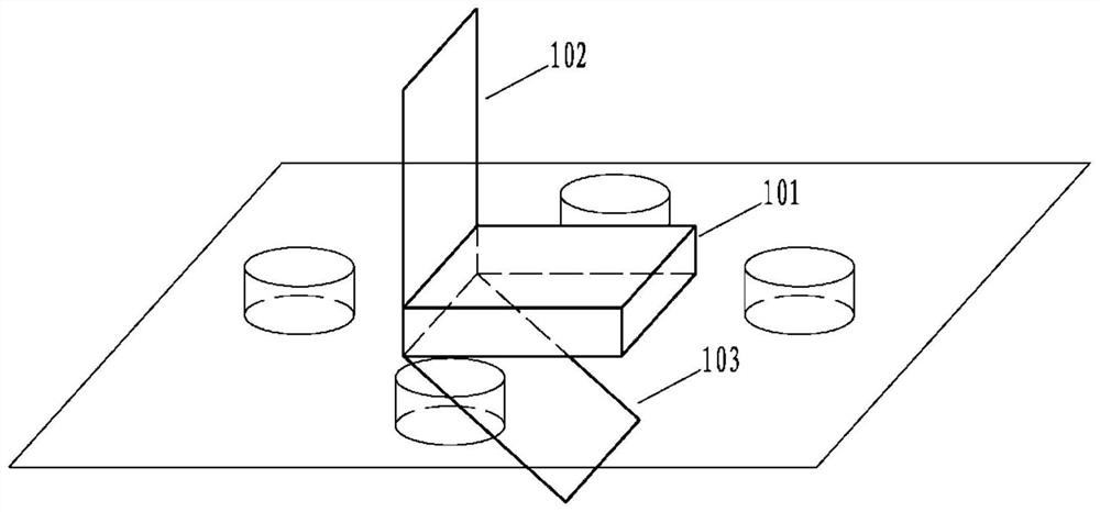
[0082] Such as Figure 1~Figure 12 As mentioned above, a kind of thermal cycle precise temperature control gradient carbonization equipment is provided with more than one vibrating flap 3 inside the equipment, and each vibrating flap 3 is arranged up and down, and a heating device, the heating port of the heating device is located on both sides of the vibrating flap 3; the vibrating flap 3 has the effect of vibrating and rolling the sludge on the plate surface; the heating device makes the temperature in the equipment have a gradient Transformation, the hot air flow in the equipment is internally circulated. The heating device is a burner 8 or a stainless steel electric heating tube, a ceramic electr...

Embodiment 1

[0093] The low-temperature carbonization process requires a treatment capacity of 850 kg / h for dry water body dredging sludge sludge biomass mixture (biomass content is 2%):

[0094] 1) The furnace body 2 of the vertical sludge carbonization equipment is equipped with 16 vibration flaps 3, 8 burners 8, and 8 temperature sensors 9; the central control system 12 controls the 8 burners 8 to start at the maximum power, and the opposite vertical sewage The furnace body 2 of the peatization equipment is preheated; the preheating target temperature is up to 300°C, and the eight burners 8 are started at the same time. When reaching 240°C, the second burner 8 is closed, and so on, until the temperature of the lowest two layers reaches 300°C, and the temperature in the carbonization furnace cavity 201 is fed back in real time by the temperature sensor 9;

[0095] 2) After the preheating temperature reaches 300°C, the temperature sensor 9 feeds back information to the central control sys...

Embodiment 2

[0104] The high-temperature rapid carbonization process requires a treatment capacity of 1200 kg / h for dry printing and dyeing sludge (the printing and dyeing sludge contains biomass, with a content of about 2%):

[0105] 1) Furnace body 2 of vertical sludge carbonization equipment is equipped with 6 vibration flaps 3, 6 burners 8, and 6 temperature sensors 9; the central control system 12 controls 6 burners 8 to start at maximum power, vertical sludge The preheating target temperature of the carbonization equipment furnace body 2 is up to 600°C, and the six burners 8 are started at the same time. When the temperature of the uppermost layer reaches 500°C, the uppermost burner 8 is turned off. Two burners 8 are closed, and so on, until the temperature of the lowest layer reaches 600 ° C, the vibration flap 3 is adjusted to a horizontal state and starts to oscillate, and the temperature in the carbonization furnace cavity 201 is fed back in real time by the temperature sensor 9; ...


PUM

PropertyMeasurementUnit
heightaaaaaaaaaa
diameteraaaaaaaaaa
lengthaaaaaaaaaa

Abstract

The invention discloses thermal cycle accurate temperature control gradient carbonization equipment and a method for sludge treatment. According to the equipment, more than one vibration turning plate is arranged in the furnace body of the vertical sludge carbonization equipment, the vibration turning plates are arranged vertically, a heating device is arranged on the outer wall surface of the equipment, and heating ports of the heating device are positioned on the two sides of the vibration turning plate; the vibration turning plate has the effects of vibrating and turning the sludge on the plate surface; the heating device enables the temperature in the equipment to have gradient transformation, and hot air flow in the equipment circularly flows in the equipment. The vertical structure plays a role in internal circulation of heat, the heating device enables the temperature in the equipment to have gradient transformation, hot air in the equipment flows in an internal circulation mode, sludge on the topmost layer falls into the next layer after being pyrolyzed at the highest temperature, and the lower layer enables the sludge to be continuously heated. The equipment also has an incineration mode, and the sludge can be incinerated.

Description

technical field [0001] The invention relates to the technical field of sludge and biomass treatment, in particular to a thermal cycle precise temperature control gradient carbonization equipment and a method for sludge pyrolysis. Background technique [0002] The treatment process of sewage and wastewater will produce a large amount of waste sludge, which contains a large amount of organic matter, heavy metals, phosphorus, germs and insect eggs. If it is not disposed of properly, the waste sludge will further pollute and damage the environment. [0003] Traditional sludge treatment and disposal methods include ocean dumping, landfilling and sludge incineration. However, using these methods to treat and dispose of sludge, there are secondary pollution problems: ocean dumping and landfilling make the harmful substances contained in the sludge re-released; landfills occupy a large area; sludge incineration produces a large amount of toxic and harmful gases , a large amount of ...

Claims


Application Information

Patent Timeline
Patent Type & Authority Applications(China)
IPC IPC(8): C02F11/10F23G5/027F23G5/08F23G5/10F23G5/44F23G5/50F23G7/00F23N5/02
CPCC02F11/10F23G5/027F23G5/08F23G5/10F23G5/444F23G5/50F23G7/001F23N5/02Y02W10/40
Inventor 利锋
Owner 博仕燊环保科技(广州)有限公司
Why Eureka
Try Eureka