Mobile integrated dual-flow air-cooled reactor system and its working method

An air-cooled reactor, dual-process technology, applied in steam applications, machines/engines, steam engine installations, etc., can solve problems affecting reactor neutron economy, strict requirements for rotating shaft materials, reactor safety issues, etc., to reduce material performance and processing and manufacturing technical requirements, small size, and the effect of equipment redundancy and safety

Active Publication Date: 2022-03-22
XI AN JIAOTONG UNIV
View PDF0 Cites 0 Cited by
  • Summary
  • Abstract
  • Description
  • Claims
  • Application Information

AI Technical Summary

Problems solved by technology

[0004] The one-way flow design of the coolant tends to lead to a higher average temperature near the outlet end of the long-term operating air-cooled reactor, while the average temperature at the inlet end is lower, which puts stricter high temperature resistance requirements on the materials at the reactor outlet end; the common compressor - The common shaft of the gas turbine runs through the reactor design, so that the shaft operates in a high-temperature and high-irradiation environment for a long time, which not only has strict requirements on the material of the shaft, but also absorbs neutrons from the material of the shaft and easily affects the neutron economy of the reactor; while using a single set of compressor-gas turbine The design mode of the main circuit of the unit is prone to the situation that when the compressor or the gas turbine has a shaft stuck accident, the core heat cannot be exported and the core melts.
In addition, the design of a single waste heat recovery power generation circuit is likely to cause waste heat energy waste and even cause reactor safety problems when a part of the circuit fails

Method used


Image

  • Mobile integrated dual-flow air-cooled reactor system and its working method
  • Mobile integrated dual-flow air-cooled reactor system and its working method

Examples


Embodiment Construction

[0024] The structure of the present invention will be described in detail below in conjunction with the drawings and specific embodiments.

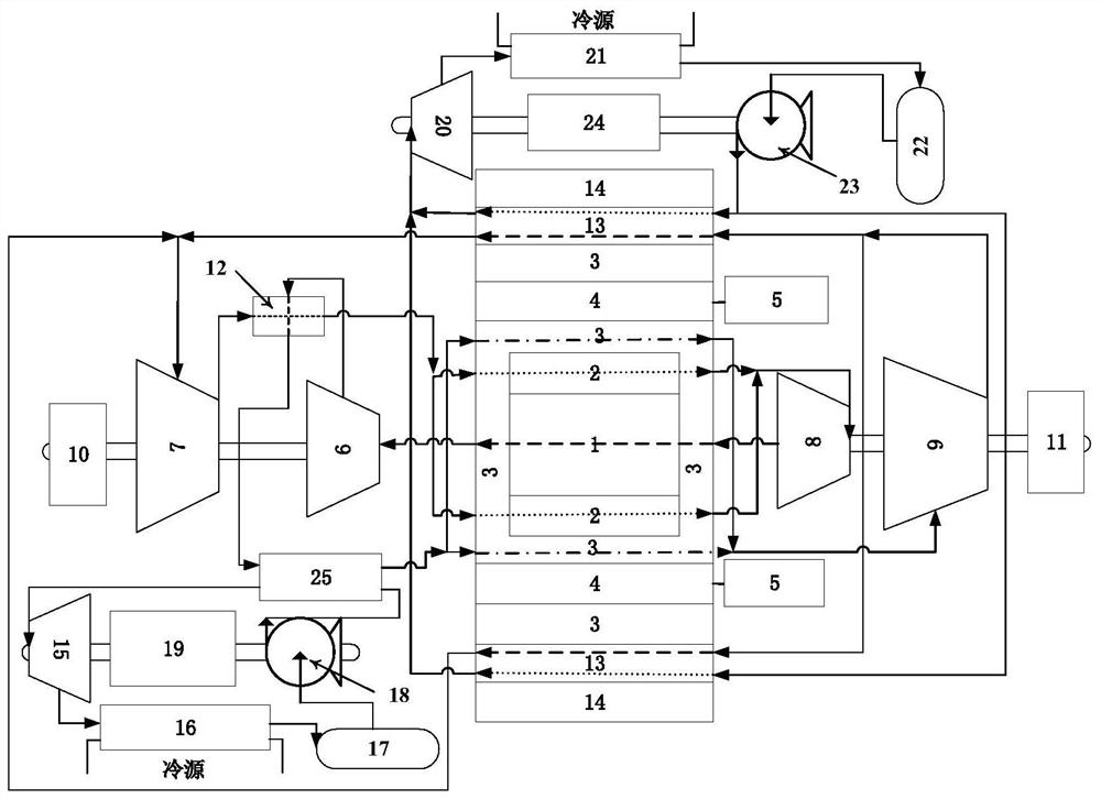
[0025] Such as figure 1 As shown, a mobile integrated double-flow air-cooled reactor system of the present invention adopts Brayton-Organic Rankine combined cycle, and the whole system includes an air-cooled reactor part, a main power generation part and an ORC waste heat power generation part, and the air-cooled reactor The part includes a reactor fuel tank, a reflective layer 3, a control drum 4, a drum driving mechanism 5, and a radiation shielding layer 14 from the inside to the outside. The reactor fuel tank is composed of an inner fuel tank 1 and an outer fuel tank 2. The inner fuel tank The outer fuel tank 2 is arranged on the periphery of the tank 1, the radially outer tank wall of the inner fuel tank 1 is closely attached to the radially inner tank wall of the outer fuel tank 2, and the inner fuel tank 1 and the outer fuel tank 2...


PUM


Abstract

The mobile integrated dual-flow gas-cooled reactor system and its working method adopt Brayton-Organic Rankine combined cycle. The whole system includes the gas-cooled reactor part, the main power generation part and the ORC waste heat power generation part; the core part of the gas-cooled reactor part is composed of internal The internal and external fuel tanks are composed of internal and external fuel tanks with different coolant pressures and opposite flow directions. The internal and external fuel tanks are arranged in the reflective layer with coolant flow channels. The axial ends of the reflective layer are respectively connected to the coaxially designed gas turbine, The compressor and the power generation unit constitute the main power generation part together with the regenerator; the ORC waste heat power generation part is composed of a two-stage ORC waste heat power generation circuit and is coupled with the main power generation part for waste heat discharge and recycling of the core; the system uses multiple sets of energy Using equipment, integrated dual-process and fuel tank design, it can contain fission products, meet equipment safety redundancy requirements and realize energy cascade utilization, and has the characteristics of compact size, high safety and high energy utilization.

Description

technical field [0001] The invention belongs to the technical field of nuclear reactor engineering, and in particular relates to a mobile integrated double-flow air-cooled reactor system cooled by gas working medium and a working method thereof. Background technique [0002] A gas-cooled reactor refers to a reactor that uses a gas coolant to cool reactor fuel blocks or fuel assemblies. Common cooling gases include pure helium, helium-xenon mixed gas, and supercritical carbon dioxide. Compared with liquid metal-cooled reactors (such as sodium-cooled fast reactors and lead-cooled fast reactors), the coolant used in gas-cooled reactors has good chemical stability and is not easily activated to produce toxic and harmful substances during operation. Compared with the currently popular pressurized water reactor, the thermal efficiency of the air-cooled reactor is high (about 40%) and the coolant will not change phase even under accident conditions, so the safety is also very high....

Claims


Application Information

Patent Timeline
Patent Type & Authority Patents(China)
IPC IPC(8): F01K13/00F01K27/00F01K17/02F01K25/08F01K7/02F01D15/10F01D15/08
CPCF01K13/00F01K27/00F01K17/02F01K25/08F01K7/02F01D15/10F01D15/08
Inventor 吴宏春雷铠灰郑友琦杜夏楠王永平
Owner XI AN JIAOTONG UNIV
Why Eureka
Try Eureka