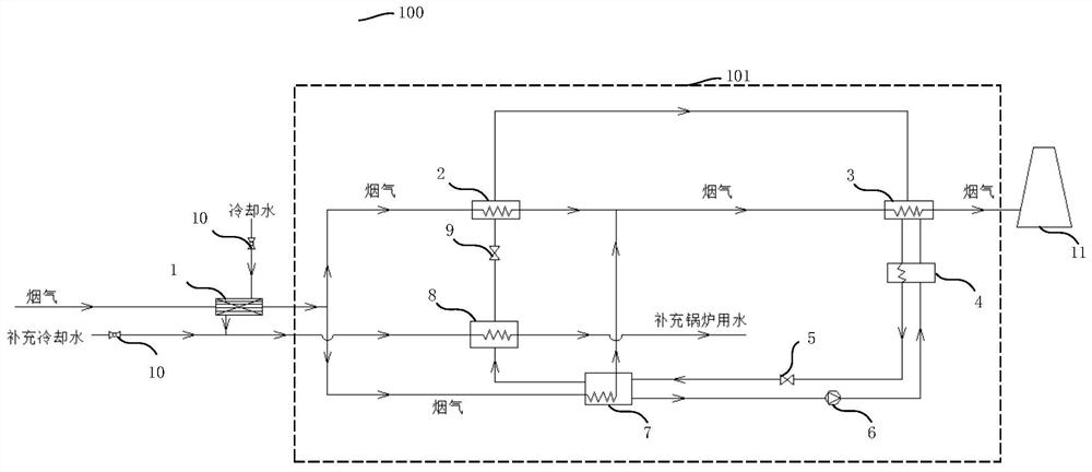
[0023] In the following, only some exemplary embodiments are briefly described. As those skilled in the art would realize, the described embodiments may be modified in various different ways, all without departing from the spirit or scope of the present invention. Accordingly, the drawings and descriptions are to be regarded as illustrative in nature and not restrictive.
[0024] In describing the present invention, it is to be understood that the terms "center", "longitudinal", "transverse", "length", "width", "thickness", "upper", "lower", "front", " Back", "Left", "Right", "Straight", "Horizontal", "Top", "Bottom", "Inner", "Outer", "Clockwise", "Counterclockwise", etc. or The positional relationship is based on the orientation or positional relationship shown in the drawings, which is only for the convenience of describing the present invention and simplifying the description, rather than indicating or implying that the referred device or element must have a specific orientation, be constructed and operated in a specific orientation, Therefore, it should not be construed as limiting the invention. In addition, the terms "first" and "second" are used for descriptive purposes only, and cannot be understood as indicating or implying relative importance or implicitly specifying the quantity of indicated technical features. Thus, a feature defined as "first" or "second" may explicitly or implicitly include one or more of said features. In the description of the present invention, "plurality" means two or more, unless otherwise specifically defined.
[0025] In the description of the present invention, it should be noted that unless otherwise specified and limited, the terms "installation", "connection" and "connection" should be understood in a broad sense, for example, it can be a fixed connection or a detachable connection. Connected, or integrally connected: it can be mechanically connected, or electrically connected, or can communicate with each other; it can be directly connected, or indirectly connected through an intermediary, and it can be the internal communication of two components or the interaction of two components relation. Those of ordinary skill in the art can understand the specific meanings of the above terms in the present invention according to specific situations.
[0026] The following disclosure provides many different embodiments or examples for implementing different structures of the present invention. To simplify the disclosure of the present invention, components and arrangements of specific examples are described below. Of course, they are only examples and are not intended to limit the invention. Furthermore, the present disclosure may repeat reference numerals and/or reference letters in different instances, such repetition is for simplicity and clarity and does not in itself indicate a relationship between the various embodiments and/or arrangements discussed. In addition, various specific process and material examples are provided herein, but one of ordinary skill in the art may recognize the use of other processes and/or the use of other materials.
[0027] The preferred embodiments of the present invention will be described below in conjunction with the accompanying drawings. It should be understood that the preferred embodiments described here are only used to illustrate and explain the present invention, and are not intended to limit the present invention.
[0028] Combine below Figure 1-Figure 3 Embodiments of the present invention are described in detail.
[0029] figure 1 A schematic structural diagram of a system 100 for recovery and utilization of flue gas waste heat and water according to an embodiment of the present invention is shown. like figure 1 As shown, the system 100 for recovery and utilization of flue gas waste heat and water includes: a film condenser 1 and an absorption heat pump cycle system 101 connected to the film condenser 1, and the absorption heat pump cycle system 101 utilizes the 1 The flue gas is used as a heat source.
[0030] Absorption heat pump circulation system 101 comprises: evaporator 2, absorber 3, heat exchanger 4, solution pump 6, regenerator 7 and condenser 8; The evaporator 2 and the regenerator 7 are all connected with the absorber 3, the heat exchanger 4 is respectively connected to the regenerator 7 and the absorber 3, and a solution pump 6 is also arranged between the heat exchanger 4 and the regenerator 7.
[0031] The absorption heat pump cycle system 101 also includes: a throttle valve 5, which is provided between the heat exchanger 4 and the regenerator 7, and between the evaporator 2 and the condenser 8 . The throttle valve 5 is used to control the flow rate of fluid or gas in the pipeline.
[0032] In the flue gas system, the high-temperature wet flue gas is dehumidified, cooled, and reheated before being discharged out of the chimney 11 . In the process of high-temperature wet flue gas flowing from the flue outlet to the chimney 11, it is firstly dehumidified by the film condenser 1. For example, the dehumidification efficiency of the flue gas is preset to be 20-40%, and the flue gas becomes unsaturated after being dehumidified by the film condenser 1. The flue gas in the unsaturated state is divided into two parts, one part of the flue gas passes through the evaporator 2, as the heating source of the evaporator 2 and cools down after exchanging heat with the evaporator 2; the other part of the flue gas passes through the regenerator 7 , as the driving heat source of the regenerator 7 and cool down after exchanging heat with the regenerator 7. The two parts of the flue gas after the heat exchange and cooling of the evaporator 2 and the regenerator 7 are combined and flow to the absorber 3, and the temperature of the flue gas after the heat exchange and cooling is heated by the absorber 3, for example, to 80-100 ° C, the temperature The raised flue gas is finally discharged into the atmosphere through the chimney 11. In this process, the film condenser 1 removes the water vapor in the flue gas, so no or less water vapor is condensed and precipitated during the cooling process of the flue gas.
[0033] figure 2 A schematic structural view of a film condenser 1 according to an embodiment of the present invention is shown, as figure 2 As shown, the inside of the membrane 15 is flowing cooling water, and the outside of the membrane 15 is high-humidity flue gas. When the high-humidity flue gas passes through the surface of the diaphragm 15, through the capillary condensation mechanism of the diaphragm 15 and the diffusion and mass transfer characteristics of the diaphragm 15 surface, under the action of the pressure difference between the inside and outside of the diaphragm 15, the separation of liquid and vapor is realized, and finally the residual heat of the flue gas and water recovery. The film condenser 1 includes a plurality of membranes 15, and the membranes 15 are provided with hole channels. The pressure inside the membrane 15 is lower than the pressure outside the membrane 15, so the inside of the membrane 15 forms a negative pressure relative to the outside, so that the moisture in the flue gas flowing outside the membrane 15 is "sucked" into the membrane 15 middle. The film condenser 1 utilizes the capillary condensation characteristics and surface diffusion and mass transfer characteristics of the diaphragm 15, as well as the pressure difference between the interior and exterior of the diaphragm 15, to realize the liquid and vapor separation of the flue gas, and the removal of moisture and waste heat in the flue gas. Efficient recycling. Preferably, the inside of the diaphragm 15 has a vacuum degree of 0.01-0.1Mpa.
[0034] image 3A schematic structural diagram of the diaphragm 15 according to an embodiment of the present invention is shown, as image 3 As shown, the diaphragm 15 includes: a separation layer 12 , a support layer 13 and a structural layer 14 , and the separation layer 12 , the support layer 13 and the structural layer 14 all have holes. Preferably, the diaphragms are connected in series.
[0035] Cooling water flows evenly in the diaphragm 15. When the flue gas passes through the surface of the diaphragm 15, the water vapor in the flue gas will condense when it encounters the diaphragm 15 with a lower temperature on the one hand, and on the other hand, will condense through the tiny pores on the surface of the diaphragm 15. Condensation condenses into tiny droplets. Due to the pressure difference between the inside and outside of the diaphragm 15, for example, a certain negative pressure value is maintained in the diaphragm 15, combined with the high water permeability of the diaphragm 15, the droplets condensed on the surface of the diaphragm 15 penetrate quickly. To the inside of the membrane 15, as the condensation continues to occur, the micropores on the surface of the membrane 15 are gradually filled with condensed droplets, and continue to penetrate into the inside of the membrane 15 to form condensed water. During the process of recovering the flue gas, the moisture in the flue gas condenses on the surface of the diaphragm 15 to form liquid droplets and penetrates and transfers to the interior of the diaphragm 15. At the same time, circulating cooling water flows inside the diaphragm 15, so a part of the flue gas The heat is also transferred to the cooling water inside the diaphragm 15 through heat and mass exchange, thereby realizing the recovery of moisture and heat in the flue gas.
[0036] During the transmission process, since the porous channel of the diaphragm 15 is filled with the condensable gas water vapor in the flue gas, the non-condensable gas is prevented from passing through, and the recovered water quality is kept good. In the process of recovering flue gas, the separation layer 12 is the key to realizing water recovery, so preferably, the size of the pores on the separation layer 12 is 10-200 nm.
[0037] The absorption heat pump circulation system 101 uses the flue gas dehumidified by the film condenser 1, such as the medium-temperature flue gas at 70°C-90°C, as the heat source for the evaporator 2 and the regenerator 7, and the regenerator 7 absorbs the heat of the flue gas and regenerates The refrigerant in the condenser 7 evaporates, the refrigerant passes through the condenser 8, exchanges heat with the cooling water flowing through the condenser 8, and then enters the evaporator 2 through the throttle valve 9; the refrigerant absorbs in the evaporator 2 The heat of the flue gas enters the absorber 3, and the refrigerant exchanges heat with the flue gas in the absorber 3. The refrigerant releases heat to heat the low-temperature flue gas, then cools down and condenses, and is combined with the absorbent in the absorber 3 (such as lithium bromide concentrated solution); the mixed refrigerant and absorbent in the absorber 3 pass through the heat exchanger 4, and then are sent to the regenerator 7; after the regenerator 7 absorbs the heat of the flue gas, the refrigerant evaporates and flows to the condenser 8, and the absorbent Then return to the absorber 3 after passing through the solution pump 6 and the heat exchanger 4. This cycle goes on and on to complete the cycle process in which the absorption heat pump absorbs heat from the flue gas with a higher temperature and then releases heat to the cooling water and the flue gas with a lower temperature.
[0038] In some embodiments, there is a lithium bromide-water solution in the regenerator 7 . After the regenerator 7 absorbs the heat of the flue gas, the refrigerant in the regenerator 7 is heated and precipitated from the lithium bromide-water solution, and the precipitated refrigerant flows to the condenser 8 .
[0039] In some embodiments, the evaporator 2 and the generator 7 in the absorption heat pump cycle system 101 use the 70-90°C medium-temperature flue gas dehumidified by the film condenser 1 as a heat source; The cooling water is mixed to form mixed cooling water, and the condenser 8 uses the mixed cooling water at 15-30°C as the low-temperature heat exchange heat source; after the low-temperature flue gas is heated in the absorber 3, the temperature of the flue gas can be increased by 10 -30°C.
[0040] The absorption heat pump cycle system 101 makes full use of the characteristics of the second type of absorption heat pump. The second type of absorption heat pump is also called a heating type heat pump, which utilizes a large amount of medium-temperature heat sources to generate a small amount of high-temperature useful heat sources. That is to use medium and low temperature heat energy to drive, use a large number of heat potential differences between medium temperature heat sources and low temperature heat sources to produce heat that is less than but higher than medium temperature heat sources, and transfer part of medium and low heat energy to higher temperature positions, thereby improving The utilization grade of heat source. In the embodiment of the present invention, a large amount of medium-temperature flue gas, such as 70°C-90°C flue gas, is used as the heating heat source of the evaporator 2 and the driving heat source of the regenerator 7, and a part of the high-temperature heat source is generated by the absorber 3 to heat the low-temperature flue gas. There is no external high-quality heat source in the process, and the absorption heat pump cycle system 101 absorbs heat at high-temperature flue gas and releases heat at low-temperature. The generation of feathers.
[0041] After recovering the moisture and waste heat of the flue gas at the film condenser 1, the cooling water is mixed with the supplementary cooling water from another pipeline, and after mixing, it flows to the condenser 8, and the temperature rises after absorbing heat in the condenser 8, for example, After 5-15 ℃, enter the boiler system to replenish water. Regulating valves 10 are provided on the supplementary cooling water pipeline and the cooling water pipeline flowing to the film condenser 1 . Therefore, the amount of water for heat exchange with the condenser 8 can be adjusted according to the amount of cooling water entering the film condenser 1 and supplementary cooling water, so as to meet the temperature and flow requirements of supplementary boiler water.
[0042] According to the embodiment of the present invention, the combination of absorption heat pump technology and membrane condensation technology is adopted to realize efficient recovery and utilization of flue gas moisture and waste heat. The absorption heat pump cycle system 101 uses the heat of the medium-temperature flue gas as the driving heat source of the regenerator 7 and the heating heat source of the evaporator 2, and then uses the heat release of the absorber 3 as the heating heat source of the low-temperature unsaturated flue gas, and utilizes the condenser 8 To heat the cooling water, make full use of the waste heat of the flue gas itself to form a cycle, no need for additional heat to heat the low-temperature flue gas, and realize the self-circulation purpose of absorbing heat from the high-temperature flue gas and releasing heat to the low-temperature flue gas;
[0043] The present invention also utilizes the membrane condenser 1 to recycle the moisture in the flue gas, the reclaimed water is relatively clean, and the reclaimed water can supplement the boiler water after being heated by the condenser 8, thereby realizing the recycling of water resources and reducing the need for heating up the reclaimed water. Heating heat reduces boiler energy consumption.
[0044] The present invention makes full use of the advantages of the organic combination of the absorption heat pump circulation system 101 and the film condenser 1 to complement each other, and realizes cascade utilization of energy and water heat recovery of wet flue gas.
[0045] The above descriptions are only preferred embodiments of the present invention, and are not intended to limit the present invention. Any modifications, equivalent replacements, improvements, etc. made within the spirit and principles of the present invention shall be included in the scope of the present invention. within the scope of protection.
[0046] Finally, it should be noted that: the above is only a preferred embodiment of the present invention, and is not intended to limit the present invention. Although the present invention has been described in detail with reference to the foregoing embodiments, for those skilled in the art, it still The technical solutions recorded in the foregoing embodiments may be modified, or some technical features thereof may be equivalently replaced. Any modifications, equivalent replacements, improvements, etc. made within the spirit and principles of the present invention shall be included within the protection scope of the present invention.