Solder ring for microwave component radio frequency connector and welding method thereof
A technology for radio frequency connectors and microwave components, applied in the field of solder rings, can solve problems such as non-conformity of tightness and concentricity, unqualified air tightness test, and central axis offset.
- Summary
- Abstract
- Description
- Claims
- Application Information
AI Technical Summary
Problems solved by technology
Method used
Image
Examples
Embodiment 1
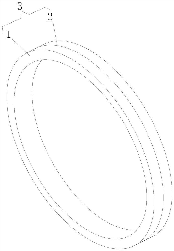
[0038] see figure 1 , a solder ring for a radio frequency connector of a microwave component, comprising a front solder ring 1 and a rear solder ring 2, the front solder ring 1 and the rear solder ring 2 are sleeved with each other to form a solder ring body 3, and the solder ring body 3 adopts a double layer The way of changing the traditional single ring as the structure of the solder ring, adding a variable structure, and multi-layer arrangement, the structure is more stable, the solder contact surface is large and the melting is uniform, the soldering quality is better, and the solder ring body 3 passes through The assembling device 4 is inserted into the hole of the radio frequency connector of the microwave assembly.
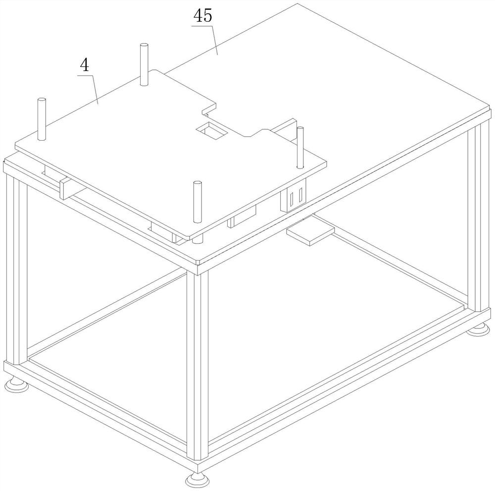
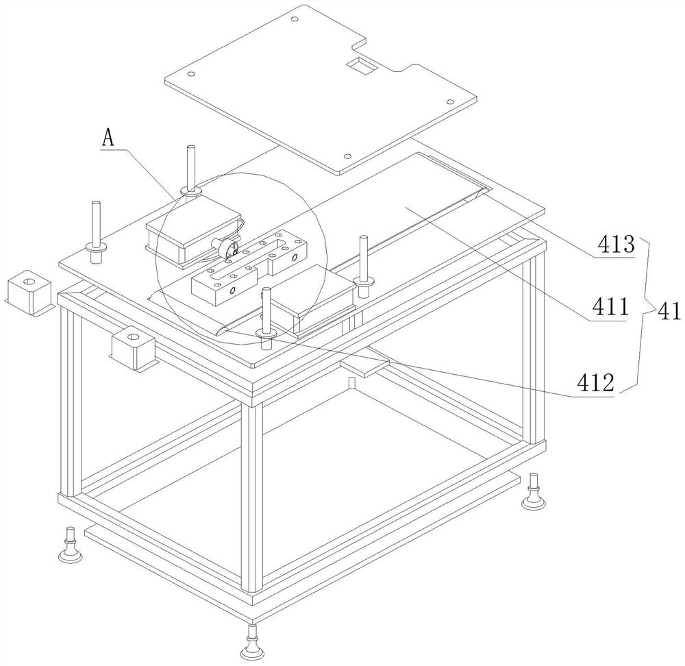
[0039] see Figure 2-3 , the assembly device 4 includes a conveying assembly 41, a positioning plate 42, a telescopic negative pressure assembly 43, a welding assembly 44 and a welding platform 45, the conveying assembly 41 is installed on the welding pla...
Embodiment 2
[0051] Among them, glass bead insulator sintering is one of the processes in the entire assembly process of microwave components, and it is also the most important process in ensuring product reliability and air tightness. Therefore, the sintering process of glass insulators has become the main direction of process research and development. Microwave components The simplest component of the single-pole double-throw switch component is based on the research. This microwave component uses 3 SMP glass insulators for welding process operations.
[0052] Both the input and output parts of the switch use SMP-JHD RF connectors, and the connectors are embedded in the box to save product installation space. Secondly, the position of the solder ring is designed after the solder is improved, please refer to Figure 9 and Figure 10 , the solder ring body 3 should match the solder diversion groove of the RF connector of the microwave component, then the size of the solder diversion groove...
Embodiment 3
[0058] like Figure 12 As shown, the microwave component RF connector SMP is soldered after using the improved technology. As shown, install the RF connector SMP-JHD into the corresponding position of the component box drawing.
[0059] Pick up the solder ring corresponding to the size of the RF connector, dip a small amount of flux, and place the solder ring on the corresponding position of the component.
[0060] Turn on the heating table and set it to 200°C. After the temperature is stable, place the microwave assembly on the heating table.
[0061] When the flux starts to evaporate, focus on the molten state of the solder. After the solder is fully melted, remove the component box and let it cool naturally.
[0062] Visually inspect the welding of the RF insulator SMP-JHD with a 75x microscope. If necessary, X-ray is used to check the penetration rate, and helium gas is used to check the semi-airtight effect.
[0063] After passing the inspection, it can flow into the ne...
PUM
 Abstract
Description
Claims
Application Information
 - R&D
- Intellectual Property
- Life Sciences
- Materials
- Tech Scout
- Unparalleled Data Quality
- Higher Quality Content
- 60% Fewer Hallucinations
Browse by: Latest US Patents, China's latest patents, Technical Efficacy Thesaurus, Application Domain, Technology Topic, Popular Technical Reports.
© 2025 PatSnap. All rights reserved.Legal|Privacy policy|Modern Slavery Act Transparency Statement|Sitemap|About US| Contact US: help@patsnap.com


