Reactor capable of controllably loading multiple catalytic materials, coating device and preparation method

A catalytic material, coating device technology, applied in chemical instruments and methods, devices for coating liquids on surfaces, chemical/physical/physical-chemical reactors, etc., can solve the problem of small flux and durability of optofluidic reactors It can improve the utilization rate of light energy and catalytic efficiency, the repeatability and durability are strong, and the production process is simple.

Active Publication Date: 2021-08-10
山东优检生物技术有限公司 +1
View PDF3 Cites 0 Cited by
  • Summary
  • Abstract
  • Description
  • Claims
  • Application Information

AI Technical Summary

Problems solved by technology

[0006] Optofluidic reactors have certain advantages in promoting catalytic reaction efficiency and exploring reaction mechanisms. Compared with traditional photoreactors, there are many improvements, but there are still the following problems: ① The materials that have achieved strong loading are limited, and new loading methods need to be developed For secure loading of various materials
The traditional coating method is suitable for most materials, but the binding force is weak, the durability and repeatability are poor, and the catalyst cannot be firmly loaded in the optofluidic reactor
The sol-gel method or chemical method can directly fix the material on the wall of the reactor, which solves the problem of weak binding force, poor durability and repeatability, but the appli

Method used


Image

  • Reactor capable of controllably loading multiple catalytic materials, coating device and preparation method
  • Reactor capable of controllably loading multiple catalytic materials, coating device and preparation method
  • Reactor capable of controllably loading multiple catalytic materials, coating device and preparation method

Examples


Embodiment Construction

[0024] The following will clearly and completely describe the technical solutions in the embodiments of the present invention with reference to the accompanying drawings in the embodiments of the present invention. Obviously, the described embodiments are only some, not all, embodiments of the present invention. Based on the embodiments of the present invention, all other embodiments obtained by persons of ordinary skill in the art without making creative efforts belong to the protection scope of the present invention.

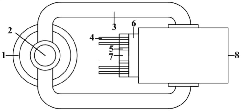
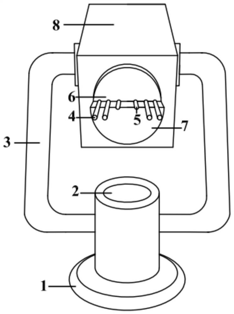
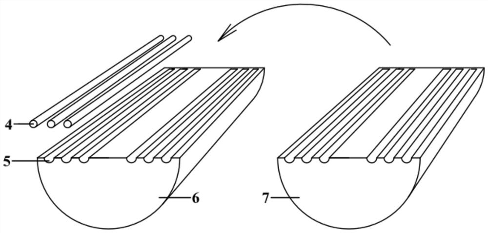
[0025] Such as Figure 1-5 A coating device for a reactor with controllable loads of various catalytic materials shown, including a centrifuge, the centrifuge includes a base 1, a rotating shaft 2 arranged on the base 1 and a rotor arranged on the rotating shaft 2 to rotate with the rotating shaft , the rotor is provided with a plurality of capillary positioning structures for fixing the capillary.

[0026] The rotor includes a rotor main body 8 and a fixing po...


PUM


Abstract

The invention discloses a reactor capable of controllably loading various catalytic materials, a coating device and a preparation method. A rotor of the coating device is provided with a plurality of capillary tube positioning structures for fixing capillary tubes, and when the capillary tubes are fixed on the capillary tube positioning structures and centrifuged by a centrifugal machine, the axis of the capillary tube is in a plane perpendicular to the axis of the rotating shaft, and the axis of the capillary tube does not coincide with any diameter of the rotating shaft. A catalytic reactor is prepared by adopting the coating equipment, a reactor capable of controllably loading multiple catalytic materials is obtained, and during centrifugation, the total length of the same capillary tube is controlled to be located on the same side of the middle axial surface of a rotating shaft perpendicular to the axis of the capillary tube. According to the invention, PDMS liquid is coated on the set area of the capillary tube, so that catalytic materials can be fixed in the set area of the capillary tube, and various catalytic materials can be loaded on the same capillary tube by changing the mounting angle of the capillary tube during each centrifugal operation.

Description

technical field [0001] The invention relates to a catalytic reactor, a coating device for the catalytic reactor and a preparation method for the catalytic reactor. Background technique [0002] Photocatalytic technology is a new type of advanced oxidation technology, which is clean and sustainable, and plays a vital role in the fields of environment, energy, and chemical industry. However, the low photocatalytic efficiency limits the application of photocatalytic technology. The photocatalytic material remains unchanged, and the reactor determines the distribution of the catalyst, the distribution of light, the photon transmission efficiency, and the transmission speed of the reactant, which play an important role in the photocatalytic efficiency. Therefore, the design of new reactors is the focus of research. [0003] Microfluidic chip is a science and technology characterized by manipulating fluid in micron-scale space. It miniaturizes and integrates the basic functions ...

Claims


Application Information

Patent Timeline
IPC IPC(8): B01J19/00B05C7/04B05C9/12B05C19/00B05D1/38B05D7/00B05D7/22
CPCB01J19/0093B05C7/04B05C19/007B05C9/12B05D7/225B05D7/586B05D1/38B01J2219/00835B01J2219/00934B01J2219/00831
Inventor 黄晓文杨崇辉
Owner 山东优检生物技术有限公司
Why Eureka
Try Eureka