
Laser fiber power supply working method based on power adaptive feedback

A technology of optical fiber power supply and working method, which is applied in photovoltaic power generation, current collectors, electric vehicles, etc., can solve the problems of poor long-term reliability of laser optical fiber power supply systems, and achieve the effect of improving long-term reliability and reducing thermal stress

Active Publication Date: 2021-08-24
GLOBAL ENERGY INTERCONNECTION RES INST EURO GMBH +4
View PDF4 Cites 4 Cited by
  • Summary
  • Abstract
  • Description
  • Claims
  • Application Information

AI Technical Summary

Problems solved by technology

[0004] The technical problem to be solved by the present invention is to overcome the problem of poor long-term reliability of the laser fiber power supply system in the prior art

Method used


Image

  • Laser fiber power supply working method based on power adaptive feedback
  • Laser fiber power supply working method based on power adaptive feedback
  • Laser fiber power supply working method based on power adaptive feedback

Examples


Embodiment Construction

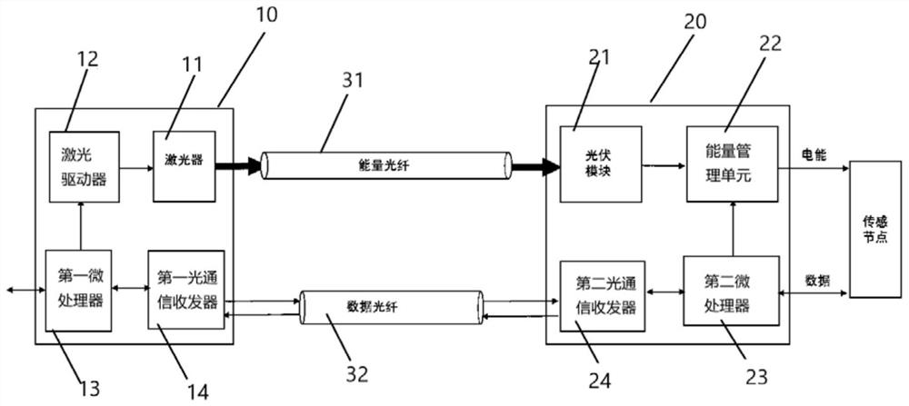
[0034] A laser fiber power supply system, refer to figure 1 , including: a laser power supply base station 10, an optical fiber and a laser power supply receiving end device 20. The laser power supply base station 10 includes: a laser 11 , a laser driver 12 , a first microcontroller 13 and a first optical communication transceiver 14 . The optical fibers include power optical fibers 31 and data optical fibers 32 . The laser power receiving end device 20 includes a photovoltaic module 21 , an energy management unit 22 , a second microcontroller 23 and a second optical communication transceiver 24 .

[0035] The laser 11 is a high-power laser diode. The laser 11 converts electrical energy into light energy, and then transmits it to the laser power receiving end device 20 through an energy fiber. The output power of the laser 11 is regulated via the current of the laser driver 12 . The laser power supply receiving end device 20 receives the laser energy output from the laser p...


PUM


Abstract

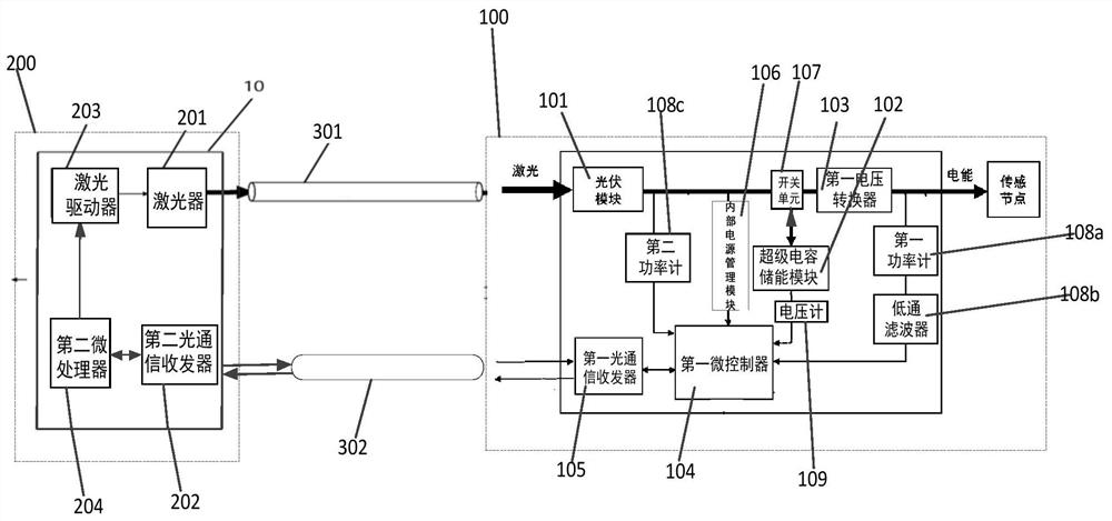
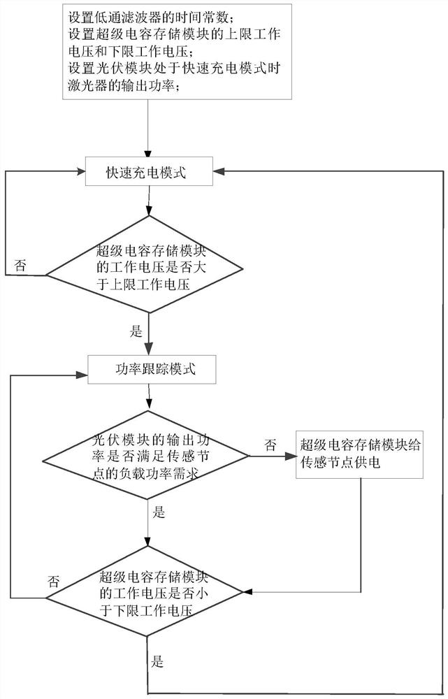
A laser fiber power supply working method based on power adaptive feedback adopts a laser fiber power supply system, the laser fiber power supply system comprises a laser, a super capacitor energy storage module, a photovoltaic module and a first microcontroller, and the photovoltaic module is suitable for supplying power to a sensing node. When the laser optical fiber power supply system is in a sensing node power supply mode, the first microcontroller executes loop feedback control on the incident laser power transmitted to the photovoltaic module by the laser based on the output power of the photovoltaic module, the power requirement of the sensing node and the working voltage of the super capacitor energy storage module, and the charging process of the photovoltaic module to the super-capacitor energy storage module and the discharging process of the super-capacitor energy storage module to the sensing node are controlled. The laser fiber power supply working method based on power adaptive feedback can improve the long-term reliability of the laser fiber power supply system.

Description

technical field [0001] The invention relates to the technical field of laser fiber power supply, in particular to a laser fiber power supply working method based on power adaptive feedback. Background technique [0002] Laser fiber powering is the preferred solution for sensing node power in high voltage (HV) environments. The reason for choosing a laser fiber power supply system instead of a conventional power supply is the requirements for electrical isolation, lightning protection, spark protection, anti-electromagnetic interference, weight reduction, and corrosion resistance. Optical power requirements for laser-fiber-powered systems for sensing applications in high-voltage environments typically range from a few watts to tens of watts, much higher than those used in optical communications. [0003] On-line monitoring of the status of key high-voltage equipment is an important means to detect abnormalities early and take remedial measures to ensure reliable operation of...

Claims


Application Information

Patent Timeline
IPC IPC(8): H02J50/30H02J50/80H02J7/35
CPCH02J50/30H02J50/80H02J7/345H02J7/35H02J7/00712Y02E10/56
Inventor 魏建国刘伟麟黄辉黄凤邓辉
Owner GLOBAL ENERGY INTERCONNECTION RES INST EURO GMBH
Learn More