Lossless Dewar flask liquid helium filling process for helium liquefier

A Dewar tank and helium technology, applied in gas/liquid distribution and storage, mechanical equipment, container filling methods, etc., can solve problems such as damage to Dewar tanks and affect the efficiency of liquid helium filling, and reduce the risk , good compression performance and heat insulation performance, easy maintenance effect

Pending Publication Date: 2021-08-31
广州市粤佳气体有限公司
View PDF9 Cites 0 Cited by
  • Summary
  • Abstract
  • Description
  • Claims
  • Application Information

AI Technical Summary

Problems solved by technology

[0002] Industrial gases have inherent physical and chemical properties, so they play a pivotal role in the national economy. The speed of promotion and application is very fast, and it has penetrated into almost all walks of life. Helium has a wide range of applications. Helium can be used in optical fiber manufacturing, etc. Communication industry, welding, analytical industry for chromatography, deep-sea diving, semiconductor, liquid crystal manufacturing, etc. shielding gas, atomic furnace, etc., liquid helium can also be used in MRI, NMR, magnetic levitation, electromagnetic propulsion ship, superconducting power transmission, extremely low temperature Physics research, etc. As an excellent superconducting and cooling medium, ultra-high-purity liquid helium is widely used in industry, aerospace and other fields. The main process of the liquid helium filling station is from liquid helium with a pressure below 10PSI The liquid phase of the tank is taken out, and it is filled into the Dewar bottle through a stainless steel vacuum hose. When the Dewar is filled, the vent valve is opened to recover the gaseous phase gas. Cause damage to the Dewar bottle, and the staff need to frequently replace or repair the Dewar bottle, thus affecting the work efficiency of liquid helium filling

Method used


Image

  • Lossless Dewar flask liquid helium filling process for helium liquefier

Examples


Embodiment Construction

[0020] The following will clearly and completely describe the technical solutions in the embodiments of the present invention with reference to the accompanying drawings in the embodiments of the present invention. Obviously, the described embodiments are only some, not all, embodiments of the present invention. Based on the embodiments of the present invention, all other embodiments obtained by persons of ordinary skill in the art without making creative efforts belong to the protection scope of the present invention.

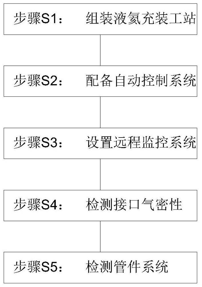
[0021] Such as figure 1 As shown, the present invention provides a non-destructive Dewar liquid helium filling process for a helium liquefaction machine, comprising the following steps:

[0022] Assemble the liquid helium filling station, assemble the helium liquefaction machine, equip the Dewar tank and multiple spare Dewar tanks, the helium gas liquefaction machine is connected to the Dewar tank through a stainless steel vacuum hose, and the interior of the ...


PUM


Abstract

The invention discloses a lossless Dewar flask liquid helium filling process for a helium liquefier. The lossless Dewar flask liquid helium filling process for the helium liquefier comprises the following steps of S1, assembling a liquid helium filling station, wherein the helium liquefier is assembled, a Dewar flask is prepared, and the helium liquefier is connected with the Dewar flask through a stainless steel vacuum hose; S2, preparing an automatic control system, wherein a pressure detection sensor is assembled in the Dewar flask, a pressure release valve is arranged on the Dewar flask, and the pressure detection sensor is externally connected with an alarm device and an emergency stop controller; S3, arranging a remote monitoring system, wherein a plurality of monitoring cameras are assembled, and an oxygen concentration alarm instrument and an acousto-optic alarm instrument are arranged in a filling workshop; S4, detecting connector gas tightness, wherein the connection gas tightness between the stainless steel vacuum hose and the Dewar flask is detected, meanwhile, the connection gas tightness between the stainless steel vacuum hose and the helium liquefier is detected, and metal wound gaskets and high-strength bolts are mounted in a combined manner at the connectors; and S5, detecting a pipe fitting system, wherein whether the Dewar flask is abnormal or not in the liquid helium filling process is detected through a temperature detector and a pressure gauge.

Description

technical field [0001] The invention relates to the technical field of liquid helium filling technology, in particular to a non-destructive Dewar tank liquid helium filling process for a helium liquefier. Background technique [0002] Industrial gases have inherent physical and chemical properties, so they play a pivotal role in the national economy. The speed of promotion and application is very fast, and it has penetrated into almost all walks of life. Helium has a wide range of applications. Helium can be used in optical fiber manufacturing, etc. Communication industry, welding, analytical industry for chromatography, deep-sea diving, semiconductor, liquid crystal manufacturing, etc. shielding gas, atomic furnace, etc., liquid helium can also be used in MRI, NMR, magnetic levitation, electromagnetic propulsion ship, superconducting power transmission, extremely low temperature Physics research, etc. As an excellent superconducting and cooling medium, ultra-high-purity liq...

Claims


Application Information

Patent Timeline
IPC IPC(8): F17C5/04F17C13/02F17C13/04F17C13/12
CPCF17C5/007F17C5/04F17C13/025F17C13/026F17C13/04F17C13/123F17C2203/0341F17C2203/0629F17C2203/0639F17C2203/0643F17C2221/017F17C2223/013F17C2223/033F17C2250/043F17C2250/0439
Inventor 黄健文苏峻峰
Owner 广州市粤佳气体有限公司
Why Eureka
Try Eureka