

Heat pump type heat management system of electric automobile
A management system and technology for electric vehicles, applied in the field of electric vehicle heat pump type thermal management systems, can solve the problems of increased high-voltage load power of the whole vehicle, overheating of the air outlet from the air conditioner, and no heat dissipation components, so as to avoid overheating of the outlet air and high heating efficiency. , the effect of low operating temperature
- Summary
- Abstract
- Description
- Claims
- Application Information
AI Technical Summary
Problems solved by technology
Method used
Image

Examples
Embodiment 1
[0056] Under cooling conditions, the system can either use refrigerant for forced cooling, or use low-temperature radiators for cooling, see the following cases a and b for details.
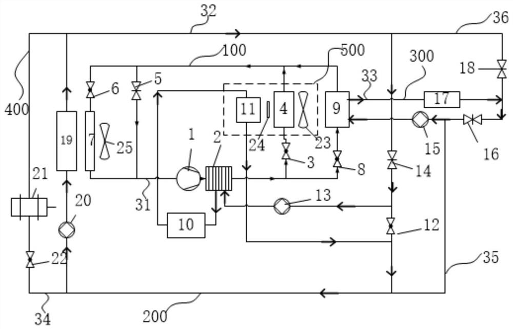
[0057] a. Under cooling conditions, when the ambient temperature is ≥ 5°C, the refrigerant realizes passenger cabin cooling + battery cooling at the same time. At this time, the state of the electric vehicle heat pump thermal management system of the present invention is as follows: figure 2 shown.
[0058]The refrigerant flow path is as follows: the compressor 1 on the refrigerant circuit 100 works to drive the refrigerant to flow to the water-cooled condenser 2, the first electronic expansion valve 3 and the third electronic expansion valve 8 are opened, the second electronic expansion valve 6 is closed, and the refrigeration The refrigerant is divided into two parallel paths, flows through the outdoor evaporator 4 and the cooling heat exchanger 9, and then merges and flows back to the compres...
Embodiment 2
[0067] Under the heating condition, the system can not only use the water heater for forced heating, but also use the heat pump for heating, and can also directly heat the power battery through the waste heat of the motor. See the following situation a, situation b, and situation c for details.
[0068] a. Under the heating condition, when the ambient temperature is ≤ -18°C, the water heater can be used to realize the heating of the passenger compartment and the heating of the battery at the same time. Figure 4 shown.
[0069] The refrigerant circuit 100 does not work.
[0070] The warm air cooling liquid circuit 200 and the battery cooling liquid circuit 300 are connected to realize a circulation circuit. Coolant Flow Path:
[0071] The first coolant shut-off valve 14 is opened, the second coolant shut-off valve 16 is closed, the third coolant shut-off valve 18 is opened, the fourth coolant shut-off valve 12 is closed, the fifth coolant shut-off valve 22 is closed, and the...
Embodiment 3
[0083] Under the conditions of high ambient humidity in spring and autumn, the heat pump air-conditioning system needs to dehumidify and reheat the humid air inside or outside the car to ensure that the air in the passenger compartment is dry and hot air, so as to avoid air pollution in the car. Fogging of car windows affects driving safety. The thermal management system can be adjusted according to the ambient temperature, see the following case a, case b, and case c for details.
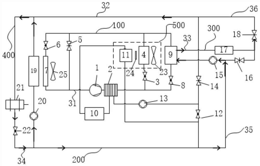
[0084] a. Under demisting conditions, when 3°C Figure 7 shown.
[0085] The flow path of the refrigerant is: the compressor 1 runs, compresses and heats up the refrigerant, drives the refrigerant to flow to the water-cooled condenser 2, and the high-temperature refrigerant dissipates heat in the water-cooled condenser 2, and dissipates heat to the warm air cooling liquid circuit 200 The refrigerant condenses and cools down, flows into the first electronic expansion valve 3 for throttling and pres...
PUM
 Abstract
Description
Claims
Application Information