Synthesis ammonia and methanol co-production method and device for improving methanol productivity

A technology for synthesizing ammonia and methanol, applied in chemical instruments and methods, ammonia preparation/separation, hydroxyl compound preparation, etc., can solve the problems of reduced methanol production capacity, inability to recycle, unstable operation, etc., so as to reduce air discharge and load. , the effect of improving methanol production

Active Publication Date: 2021-09-21
新疆心连心能源化工有限公司
View PDF6 Cites 0 Cited by
  • Summary
  • Abstract
  • Description
  • Claims
  • Application Information

AI Technical Summary

Problems solved by technology

[0002] In the existing co-alcohol process, unshifted gas is used to produce methanol, that is, there is no shift furnace in the methanol synthesis gas system. After the saturated water gas produced by gasification is cooled to separate saturated water, it is washed from the shift gas in the low-temperature methanol washing section of the ammonia synthesis system. The tower is equipped with a stream of hydrogen (i.e. post-allocation of hydrogen) to meet the requirements of methanol production. In this way, the load of the shift gas scrubber in the low-temperature methanol washing section is relatively high. When the load of the shift gas scrubber rises to 117% of the load, the operation is unstable
In addition, the high-nitrogen tail gas (containing 30% nitrogen) sent out by liquid nitrogen washing is recovered to the inlet of the second conversion furnace after the compressor increases the pressure, so that 2% of the nitrogen in the after-mixed hydrogen enters the methanol synthesis system, and the nitrogen does not participate. Methanol synthesis reaction, due to the presence of nitrogen in the methanol synthesis cycle gas, a large amount of purge gas is emptied, which cannot be recycled, reducing methanol production capacity

Method used


Image

  • Synthesis ammonia and methanol co-production method and device for improving methanol productivity

Examples


Embodiment 1

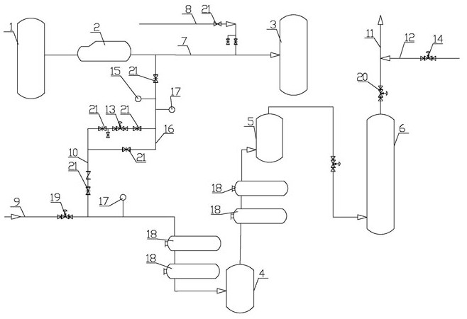
[0023] Embodiment 1: as attached figure 1 As shown, the method for synthesizing ammonia to co-produce methanol for improving methanol production capacity is carried out as follows: the shift gas generated by the first shift furnace 1 is divided into two streams, one stream of shift gas and high nitrogen tail gas (containing 30% nitrogen ) into the second shift furnace 3 together, and another stream of shifted gas merges with unshifted gas to form the pre-hydrogen mixed gas. After the first heat exchange and cooling, the pre-hydrogen mixed gas is separated by the water separation tank 4 The saturated water of the mixed gas with hydrogen is then cooled to normal temperature through the second heat exchange, and the ammonia in the mixed gas with hydrogen is removed through the ammonia washing tower 5, and the sulfide and carbon dioxide are removed through the unshifted gas washing tower 6 to obtain purified gas , after the purified gas is combined with the post-hydrogen gas from ...

Embodiment 2

[0026] Embodiment 2: as attached figure 1 As shown, the device for implementing the method for synthesizing ammonia and co-producing methanol described in Example 1 for improving methanol production capacity includes a first shift furnace 1, a medium-pressure waste heat boiler 2, a second shift furnace 3, a first heat exchange device, water The separation tank 4 and the unconverted gas scrubber 6, the converted gas outlet of the first shift furnace 1 communicates with the inlet of the medium-pressure waste heat boiler 2, and the gas outlet of the medium-pressure waste heat boiler 2 communicates with the inlet of the second shift furnace 3 The end is connected through the conversion gas pipeline 7, and the conversion gas pipeline 7 is connected with the liquid nitrogen washing recovery gas pipeline 8, and the high temperature end inlet of the first heat exchange device is connected with the untransformed gas pipeline 9, and the gas outlet of the medium pressure waste heat boiler...

Embodiment 3

[0039] Embodiment 3: the operating process of the device described in embodiment 2 is as follows:

[0040] (1) Unconverted system (including unconverted gas pipeline 9) and unconverted gas scrubber 6 depressurization: close unconverted gas control valve 19, open large low-temperature methanol to wash unconverted purified gas (that is, unconverted gas scrubber 6 ) outlet of the purified gas control valve 20 to reduce the untransformed system pressure to about 5.4MPa (that is, the outlet pressure of the water separation tank 4 is about 0.1MPa lower than the inlet pressure of the second conversion furnace 3); pay attention to the post-hydrogen distribution pipeline during depressurization 12 of the hydrogen dosing amount, make adjustments to maintain a stable flow;

[0041] (2) Pipeline pressure boost: close the front hydrogen distribution flow control valve 13 and the valve 21 of the bypass pipeline 16, slowly open the front gas distribution shaker valve (reserved valve), and pr...


PUM


Abstract

The invention relates to the technical field of synthesis ammonia and methanol co-production process and device, in particular to a synthesis ammonia and methanol co-production method and device for improving methanol productivity, the method introduces a stream of process gas subjected to a shift reaction, and the process gas is added into an inlet of a shift section non-shift gas system to form non-shift mixed gas with low nitrogen content as raw material gas for methanol synthesis. According to the method, the unconverted gas is subjected to a front hydrogen distribution mode, the rear hydrogen distribution amount is remarkably reduced, the nitrogen content in the front hydrogen distribution gas is low, so that the nitrogen content in the methanol synthesis raw material gas is reduced, the nitrogen content in the methanol synthesis circulating gas can be reduced, the emptying amount of the methanol synthesis purge gas is reduced, and the methanol yield is improved; meanwhile, the load of the shift gas washing tower at the low-temperature methanol washing section can be reduced, and the shift gas washing tower stably runs.

Description

technical field [0001] The invention relates to the technical field of synthetic ammonia and co-production of methanol technology and devices, and relates to a method and device for synthesizing ammonia and co-production of methanol for increasing methanol production capacity. Background technique [0002] In the existing co-alcohol process, unshifted gas is used to produce methanol, that is, there is no shift furnace in the methanol synthesis gas system. After the saturated water gas produced by gasification is cooled to separate saturated water, it is washed from the shift gas in the low-temperature methanol washing section of the ammonia synthesis system. The tower is equipped with a stream of hydrogen (i.e. post-allocation hydrogen) to meet the requirements of methanol production, so the load of the shift gas scrubber in the low-temperature methanol washing section is relatively high. When the load of the shift gas scrubber rises to 117% of the load, the operation is unst...

Claims


Application Information

Patent Timeline
Patent Type & Authority Applications(China)
IPC IPC(8): C07C29/152C07C29/151C01C1/04
CPCC07C29/152C07C29/1518C01C1/04C07C31/04
Inventor 孔秋福王凯周春领王宗宾张攀超冯全涛张善立
Owner 新疆心连心能源化工有限公司
Why Eureka
Try Eureka