Eureka AIR delivers breakthrough ideas for toughest innovation challenges, trusted by R&D personnel around the world.

Gas diffusion layer, preparation method and application thereof, and fuel cell

A gas diffusion layer and slurry technology, applied in fuel cells, battery electrodes, circuits, etc., can solve problems such as flooding failure, high cost, affecting fuel cell performance and service life, etc., and achieve the effect of improving peak power density

Active Publication Date: 2021-09-21
EAST CHINA UNIV OF SCI & TECH
View PDF9 Cites 0 Cited by
  • Summary
  • Abstract
  • Description
  • Claims
  • Application Information

AI Technical Summary

Problems solved by technology

[0005] The technical problem solved by the present invention is to overcome the defect that the proton exchange membrane fuel cell in the prior art is prone to flooding failure under high power and seriously affects the performance and service life of the fuel cell, and the improved method is complicated in process and high in cost, and provides A kind of gas diffusion layer and its preparation method, application and fuel cell

Method used


Image

  • Gas diffusion layer, preparation method and application thereof, and fuel cell
  • Gas diffusion layer, preparation method and application thereof, and fuel cell
  • Gas diffusion layer, preparation method and application thereof, and fuel cell

Examples


Embodiment 1

[0090] S1: Preparation of the base layer: place the carbon paper in an acetone solution for 30 minutes, take it out and put it in a 60°C oven for drying, soak it in a PTFE emulsion with a mass fraction of 10%, and then put it in the oven for drying, repeat several times times until the loading of PTFE on carbon paper reaches 30%.

[0091] Microporous layer preparation: Weigh 0.01g of ammonium chloride and add 0.02g of deionized water to form an ammonium chloride solution, take 0.03g each of SuperP, AB type carbon black and Vulcan XC-72, 8g of deionized water, 10g of isopropanol, Mix 0.6 g of 10% wt polytetrafluoroethylene emulsion, add the above ammonium chloride solution, and ultrasonically disperse for 3 hours to form a microporous layer slurry. The microporous layer slurry is sprayed onto the base layer by pressure spraying so that the loading of the conductive material is 2 mg / cm 2 , and then placed in a muffle furnace for sintering at 360°C for 1h.

[0092]S2: Wetting s...

Embodiment 2

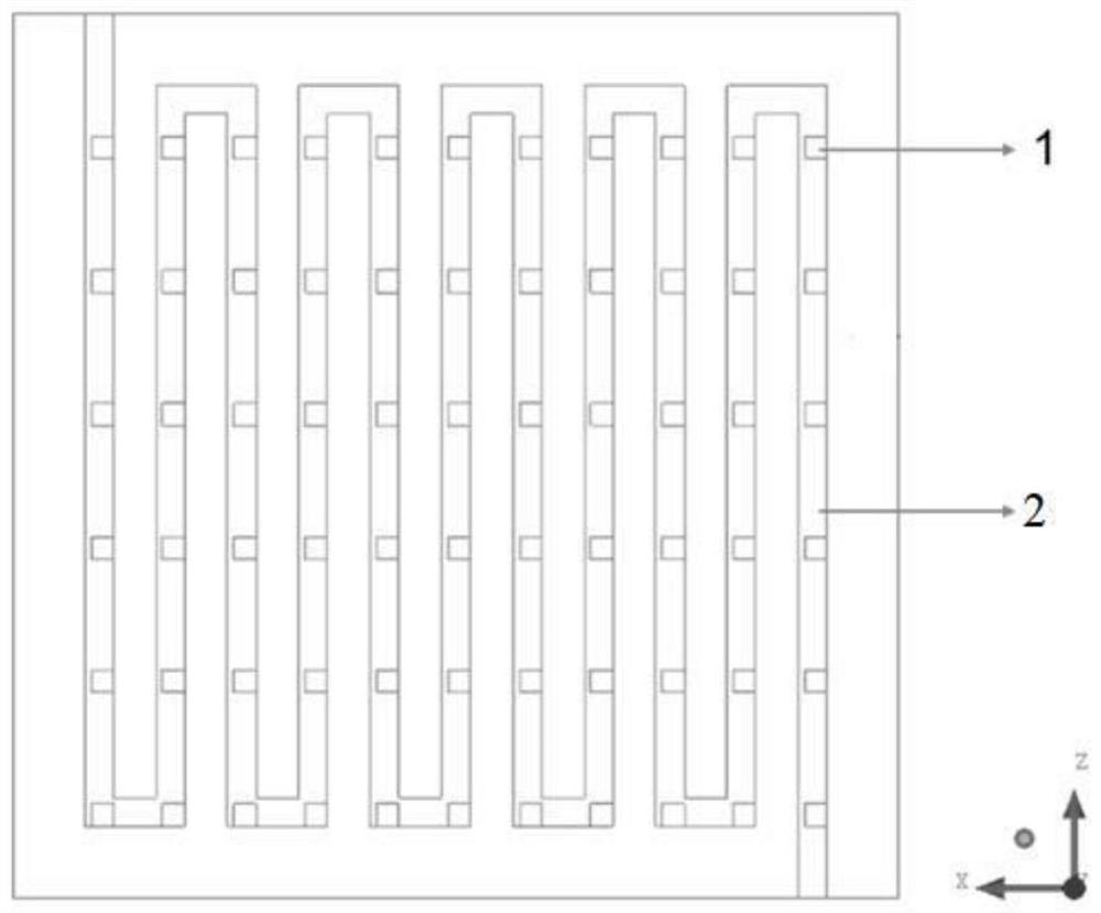
[0094] In S1, the mass of the conductive material Super P, AB carbon black, and Vulcan XC-72 is changed to 0.035g; in S2, the size of the wettability module is changed to 0.4mm*0.4mm, and the center distance is changed to 2mm. The area ratio of the flow channel is 11%, and other operations and conditions are the same as in Example 1.

Embodiment 3

[0096] In S2, the wettability reagent was changed to sodium dodecylalanine, the film-forming agent was changed to polyvinyl alcohol, the size of the wettability module was changed to 0.3mm*0.3mm, the distance between centers was changed to 3mm, and the wettability part The area ratio of the flow channel is 6%, and other operations and conditions are the same as in Example 1.


PUM

PropertyMeasurementUnit
penetration depthaaaaaaaaaa

Abstract

The invention discloses a gas diffusion layer, a preparation method and application thereof, and a fuel cell. The gas diffusion layer comprises a substrate layer and a microporous layer, and the microporous layer is loaded on the substrate layer; the gas diffusion layer comprises a wettability part, the wettability part comprises a plurality of wettability modules which are arranged at intervals, the arrangement track of the wettability modules corresponds to a flow channel of the bipolar plate of the fuel cell, each wettability module is loaded with a wettability reagent, and the wettability reagent permeates the substrate layer and the microporous layer, so water on the surface of the microporous layer directly enters the flow channel through the wettability part. The liquid water breakthrough pressure of the gas diffusion layer provided by the invention is greatly reduced, so that water generated by a catalyst layer can be quickly discharged from the gas diffusion layer, the possibility of water logging is reduced, the peak power density of the fuel cell is improved, and the preparation method is simple, low in cost and easy to industrialize.

Description

technical field [0001] The invention relates to a gas diffusion layer, its preparation method, application and fuel cell. Background technique [0002] Proton exchange membrane fuel cell (PEMFC), as an energy conversion device, has the advantages of high energy conversion efficiency, less clean pollution, and high specific energy, and plays an irreplaceable role in the development of hydrogen energy economy. With the development of economy and society, the power density of fuel cells is required to be higher and higher, and the gas diffusion layer plays an important role in improving the power density of fuel cells. During the operation of the fuel cell, the water produced in the cathode catalytic layer is removed through the gas diffusion layer, and the oxygen in the flow channel also passes through the gas diffusion layer to reach the cathode for redox reaction. During the operation of the fuel cell, due to the temperature of 60-100 ° C, water vapor condenses on the surfa...

Claims


Application Information

Patent Timeline
Patent Type & Authority Applications(China)
IPC IPC(8): H01M4/86H01M4/88H01M8/0247H01M8/0258H01M8/1004
CPCH01M4/8605H01M4/8807H01M8/0247H01M8/0258H01M8/1004H01M2008/1095Y02E60/50
Inventor 姜海波李春忠张文会陈爱平周鹰杰陆吉源毕瓅元
Owner EAST CHINA UNIV OF SCI & TECH
Why Eureka
Eureka Blog
Learn More