Ultra-wideband dielectric resonator antenna and communication equipment

A dielectric resonator and ultra-broadband technology, which is applied to antennas, antenna grounding devices, antenna supports/mounting devices, etc., can solve the problems of difficult processing, large cross-frequency bands, and increased thickness, so as to facilitate mass production and promotion. The effect of large frequency coverage and regular shape

Pending Publication Date: 2021-09-24
SHENZHEN SUNWAY COMM
View PDF0 Cites 0 Cited by
  • Summary
  • Abstract
  • Description
  • Claims
  • Application Information

AI Technical Summary

Problems solved by technology

[0003] According to 3GPP TS38.101-2 5G terminal radio frequency technical specification and TR38.817 terminal radio frequency technical report, 5GmmWave frequency bands include N257 (26.5-29.5GHz), N258 (24.25-27.25GHz), N260 (37-40GHz), N261 (27.5-28.35GHz) and the newly added N259 (39.5-43GHz), which span a large frequency band, traditional antennas cannot meet the communication needs in 5G scenarios, and broadband antennas or dual-band antennas need to be designed to cover these frequency bands
[0004] The conventional millimeter-wave broadband antenna based on PCB, including the antenna form is PATCH (patch antenna), dipole (dipole antenna), SLOT (slot antenna), etc., in the case of bandwidth requirements covering N257, N258 and N260, It will increase the thickness of the PCB. At this time, the number of layers also needs to be more adaptable, and because in the millimeter frequency band, multi-layer PCBs have high requirements for the accuracy of holes, line widths, and line spacing, and the processing is difficult.

Method used


Image

  • Ultra-wideband dielectric resonator antenna and communication equipment
  • Ultra-wideband dielectric resonator antenna and communication equipment
  • Ultra-wideband dielectric resonator antenna and communication equipment

Examples


Embodiment 1

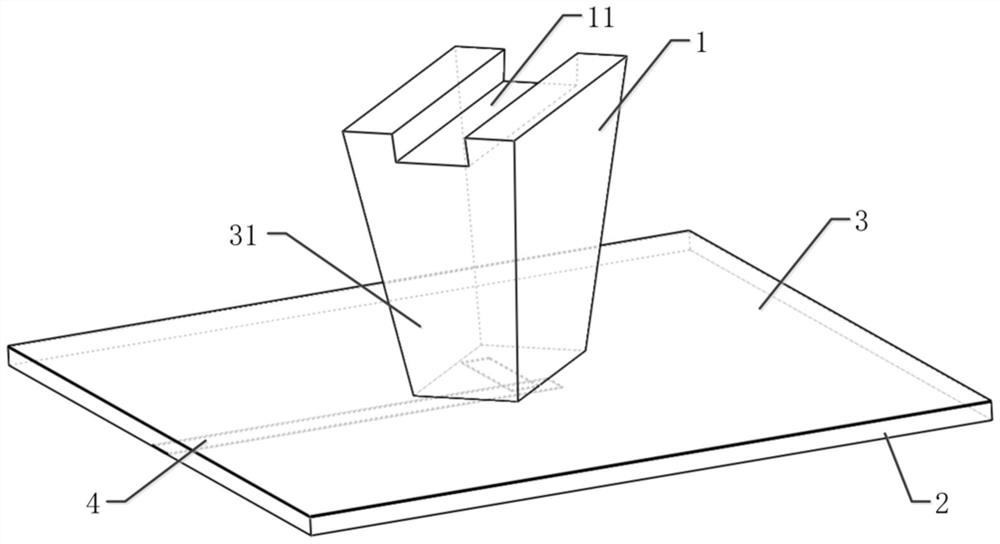
[0042] Please refer to figure 1 and figure 2 , Embodiment 1 of the present invention is:

[0043] An ultra-broadband dielectric resonator antenna (dielectric resonator antenna, DRA), including a dielectric resonator 1, a dielectric substrate 2 and a feed network;

[0044] The dielectric resonator is a trapezoidal platform, and the smaller bottom surface of the two bottom surfaces of the trapezoidal platform is connected to one side of the dielectric substrate; the other side of the dielectric substrate is connected to the feed network;

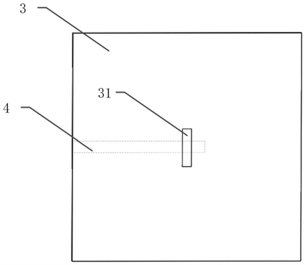
[0045] Specifically, it also includes a metal ground 3, the metal ground is arranged on the side of the dielectric substrate close to the trapezoidal platform, and the metal ground is provided with a gap 31; the bottom surface of the trapezoidal platform with a smaller area covers the gap;

[0046] Wherein, the feeding network includes a microstrip line 4, one end of the microstrip line is aligned with the side of the dielectric substrate, ...

Embodiment 2

[0050] Please refer to Figure 1-Figure 6 , the second embodiment of the present invention is:

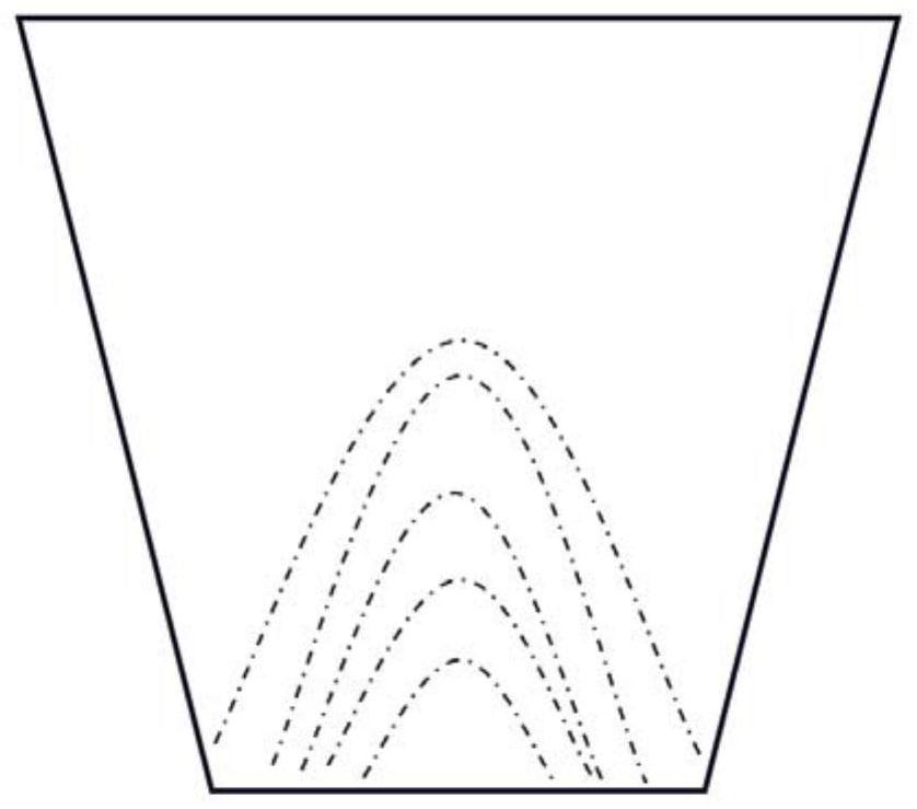
[0051] A kind of ultra-broadband dielectric resonator antenna, its difference with embodiment one is that the lower bottom surface of the trapezoidal platform is provided with a groove 11, and the groove is parallel to the side of the lower bottom surface and is as long as the side;

[0052] Among them, the specific dimensions of the dielectric resonator are: height 3.7-4.2mm; the bottom surface with a smaller area is 2.4-2.6mm long and 1.4-1.6mm wide; the bottom surface with a larger area is 3.5-4.5mm long and 2.3-2.5mm wide;

[0053] The length of the groove is equal to the length of the bottom surface with a larger area, the width is 0.9-1.1mm, and the height is less than or equal to 0.5mm;

[0054]In an optional embodiment, the specific dimensions of the dielectric resonator are: a height of 3.9mm, a bottom surface with a smaller area is 2.52mm long, and a width of 1.5mm; a bo...

Embodiment 3

[0058] Please refer to figure 2 , Embodiment three of the present invention is:

[0059] A communication device includes the ultra-wideband dielectric resonator antenna in Embodiment 1 or Embodiment 2.

[0060] In summary, the present invention provides an ultra-broadband dielectric resonator antenna and communication equipment, using a dielectric resonator shaped as a trapezoidal platform, matching its smaller bottom surface with the gap of the metal ground, and matching the larger bottom surface As a radiating surface, it increases the radiation area while exciting the TE111 mode and TE113 mode, and can cover the N257 and N260 frequency bands. Moreover, a groove is set on the bottom surface of the trapezoidal table with a larger area, so that the equivalent of the dielectric resonator The overall dielectric constant of the radiator decreases, the gain of the antenna is improved after the groove is dug, and a new TE121 mode is excited on the ground, which further broadens t...


PUM


Abstract

The invention provides an ultra-wideband dielectric resonator antenna and communication equipment. The ultra-wideband dielectric resonator antenna comprises a dielectric resonator, a dielectric substrate and a feed network; the dielectric resonator is a trapezoidal table, and the bottom surface with the smaller area in the two bottom surfaces of the trapezoidal table is connected with one side of the dielectric substrate; the other side of the dielectric substrate is connected with the feed network; according to the invention, the trapezoidal table is arranged as the dielectric resonator of the ultra-wideband antenna, N257 and N260 frequency bands can be covered, the frequency coverage range is large, the requirements of 5G communication frequency bands are met, the antenna can be used in 5G equipment, the trapezoidal table is regular in shape and easy to process, mass production and popularization are facilitated, and therefore the antenna which is easy to process and meets the requirements of the 5G communication frequency bands is achieved.

Description

technical field [0001] The invention relates to the technical field of antennas, in particular to an ultra-wideband dielectric resonator antenna and communication equipment. Background technique [0002] As 5G is the research and development focus of the global industry, it has become an industry consensus to develop 5G technology and formulate 5G standards. At the 22nd meeting of ITU-RWP5D held in June 2015, the International Telecommunication Union ITU clarified three main application scenarios of 5G: enhanced mobile broadband, large-scale machine communication, and high-reliability and low-latency communication. These three application scenarios correspond to different key indicators. In the enhanced mobile bandwidth scenario, the user peak speed is 20Gbps, and the minimum user experience speed is 100Mbps. The unique high carrier frequency and large bandwidth characteristics of millimeter wave are the main means to achieve 5G ultra-high data transmission rate. [0003] ...

Claims


Application Information

Patent Timeline
Patent Type & Authority Applications(China)
IPC IPC(8): H01Q1/36H01Q1/50H01Q1/48H01Q1/12H01Q5/10H01Q5/20H01Q5/307
CPCH01Q1/36H01Q1/50H01Q1/48H01Q1/12H01Q5/10H01Q5/20H01Q5/307
Inventor 赵伟唐小兰戴令亮谢昱乾
Owner SHENZHEN SUNWAY COMM
Why Eureka
Try Eureka