Particulate filter regeneration method, controller and regeneration system

A particle trap and regeneration system technology, which is applied in the electrical control of machines/engines and exhaust treatment devices, exhaust treatment, etc., can solve problems such as long service regeneration time, reduced engine operation stability, and low regeneration efficiency , to achieve the effects of environmental air protection, improvement of operational safety, and improvement of regeneration efficiency

Active Publication Date: 2021-10-01
UNITED AUTOMOTIVE ELECTRONICS SYST
View PDF5 Cites 2 Cited by
  • Summary
  • Abstract
  • Description
  • Claims
  • Application Information

AI Technical Summary

Problems solved by technology

[0007]1. Although the fuel injection quantity is reduced while increasing the engine speed, the oxygen flow into the particulate filter is still limited due to the low load of the parking engine , resulting in a longer regeneration time of the particulate filter (about one to two hours), and low regeneration efficiency
[0008]2. Although the ignition angle is pushed back while the engine speed is increased, the temperature of the exhaust gas flowing into the particulate filter is still low due to the low load of the parked engine. High, it will also cause the particle filter to take a long time to regenerate (about one to two hours), and the regeneration efficiency is low
[0009]3. When the engine is parked, the engine runs at high speed for a long time, which increases the heat load of the engine compartment and the surrounding components of the exhaust system, which poses a safety hazard
[0010]4. In a low-oxygen environment such as a plateau area, the above method is used to regenerate the particle filter, which further reduces the stability of the engine operation, and the oxygen flow rate is also reduced , service regeneration takes longer than plain
Existing methods for regeneration of particulate traps are limited in low-oxygen environments, resulting in inefficient regeneration
[0011]5. In a low-oxygen environment, the engine runs in a lean mixture condition for a long time, which produces a large amount of nitrogen oxide emissions and pollutes the air
[0012]6. The end of the parking regeneration method is controlled by the regeneration execution time, and it is impossible to determine whether the carbon in the particle trap is completely burned. There may be particle residues, and there may be excessive Clean up the situation, causing waste

Method used


Image

  • Particulate filter regeneration method, controller and regeneration system
  • Particulate filter regeneration method, controller and regeneration system

Examples


no. 1 example ;

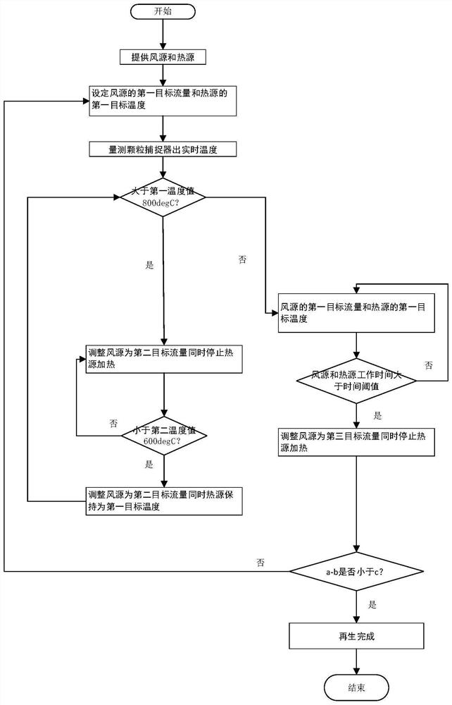
[0084] The invention provides a method for regenerating a particle trap, comprising the following steps:

[0085] S1, providing air source and heat source, the air supplied by the air source is heated by the heat source and then enters the inlet of the particle filter;

[0086] S2. Measure the real-time temperature at the outlet of the particulate filter, adjust the target air volume of the air source and the target temperature of the heat source according to the real-time temperature until the regeneration condition of the particulate filter is met, otherwise readjust the target air volume of the air source and the target temperature of the heat source.

no. 1 example

[0087] In the first embodiment of the present invention, the regeneration time of the particle trap can be shortened and the regeneration efficiency can be improved under the environment of low oxygen content through the wind source and the heat source. Adjust the target air volume of the air source and the target temperature of the heat source according to the real-time temperature until the particle trap regeneration condition is satisfied, accurately control the regeneration time of the particle trap, avoid excessive regeneration of the particle trap, and avoid insufficient regeneration of the particle trap, Prevent wastage.

no. 2 example ;

[0089] Such as figure 1 As shown, the present invention provides a particle trap regeneration method, comprising the following steps:

[0090] S2.1, setting the first target flow rate of the wind source and the first target temperature of the heat source;

[0091] The first target flow rate and the first target temperature are specified according to actual needs. It is recommended that the first target flow range is less than 200Kg / h~400Kg / h, preferably less than 300Kg / h, and the first target temperature range is: greater than or equal to 650degC, preferably equal to 650degC;

[0092] S2.2, if the real-time temperature is greater than the first temperature value, adjust the air source to the second target flow rate and stop the heat source heating;

[0093] The first temperature value and the second target flow rate are specified according to actual needs. It is recommended that the first temperature value range is: greater than or equal to 800degC, preferably equal to 800de...


PUM


Abstract

The invention discloses a particulate filter regeneration method, which comprises the following steps of: providing an air source and a heat source, wherein air supplied by the air source is heated by the heat source and then enters an inlet of a particulate filter; and measuring the real-time temperature of an outlet of the particulate filter, adjusting the target air volume of the air source and the target temperature of the heat source according to the real-time temperature until the regeneration condition of the particulate filter is met, otherwise, adjusting the target air volume of the air source and the target temperature of the heat source again. The invention further discloses a controller used for executing the steps in the particulate filter regeneration method, and a particulate filter regeneration system. Compared with the prior art, the regeneration time of the particulate filter can be shortened; and the regeneration efficiency of the particulate filter is improved. According to the invention, extra nitrogen oxide emission is not generated; environmental air protection is facilitated; excessive regeneration and insufficient regeneration of the particulate filter can be avoided; waste is avoided; and thermal damage of the particulate filter is avoided.

Description

technical field [0001] The invention relates to the field of automobiles, in particular to a method for regenerating an engine particle trap. The present invention also relates to a controller for performing the steps in the particulate trap regeneration method; and, a particulate trap regeneration system. [0002] The engine of the present invention includes a gasoline engine and a diesel engine, and the particulate filter includes a diesel particulate filter: DPF (Diesel Particulate Filter), and a gasoline engine particulate filter: GPF (Gasoline Particulate Filter). Background technique [0003] Engine pollution mainly comes from 4 components - particulate matter (PM), hydrocarbons (HCx), nitrogen oxides (NOx) and carbon monoxide (CO). Among them, the particulate matter (soot) is mostly composed of tiny particles of carbon or carbide (size less than 4-20 μm). [0004] The particulate filter reduces engine soot by more than 90%, capturing particulate emissions that are t...

Claims


Application Information

Patent Timeline
Patent Type & Authority Applications(China)
IPC IPC(8): F01N3/027F01N11/00F01N13/00
CPCF01N3/027F01N11/002F01N13/00Y02T10/40
Inventor 张虹
Owner UNITED AUTOMOTIVE ELECTRONICS SYST
Why Eureka
Try Eureka