IGCC combined heat and power generation system and method with high heat and power ratio

A combined heat and power generation and high heat technology, applied in the direction of charging system, turbine/propellant fuel delivery system, combined combustion mitigation, etc., can solve the problems of limited central heating and cooling functions, limited steam volume, low heat-to-electricity ratio, etc. Achieve the effect of reducing heating cost, lowering construction cost and high heat quality

Pending Publication Date: 2021-10-19
HUANENG CLEAN ENERGY RES INST +1
View PDF0 Cites 0 Cited by
  • Summary
  • Abstract
  • Description
  • Claims
  • Application Information

AI Technical Summary

Problems solved by technology

For IGCC power generation technology, the amount of steam that can be extracted from the steam turbine is very limited, and the heat-to-power

Method used


Image

  • IGCC combined heat and power generation system and method with high heat and power ratio

Examples


Embodiment Construction

[0028] The present invention is described in further detail below in conjunction with accompanying drawing:

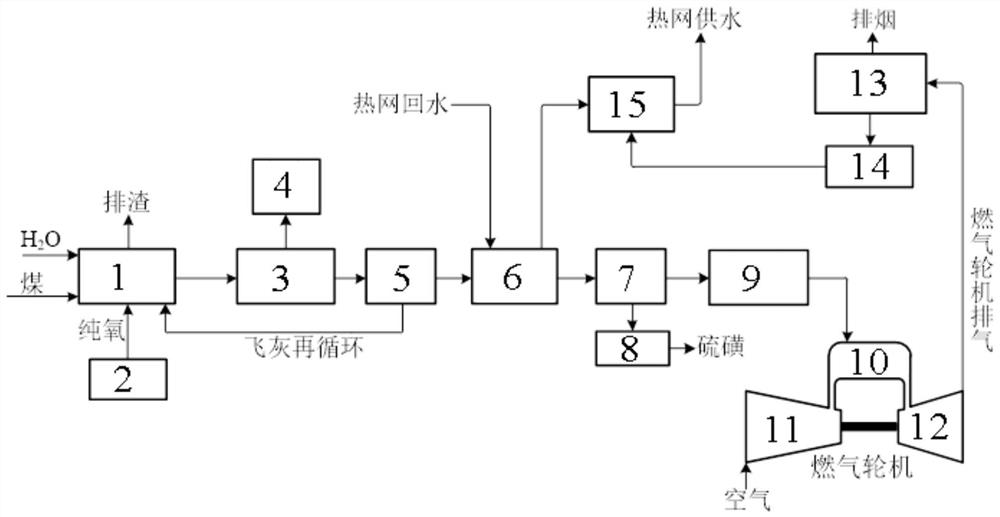
[0029] Such as figure 1 As shown, the IGCC cogeneration system with high heat-to-electricity ratio described in this application includes a gasifier 1, a chilling unit 3, a dust removal unit 5, a waste heat recovery unit 6, a desulfurization unit 7, a syngas modulation unit 9, Combustion chamber 10, turbine 12, waste heat boiler 13, steam turbine 14 and peak heater 15.

[0030] The gasifier 1 is connected with water vapor and coal, and the gasifier 1 is connected with a cryogenic air separation system 2, and the cryogenic air separation system 2 is used to input pure oxygen into the gasifier 1.

[0031] The chilling unit 3 is connected to the gray water treatment unit 4. The crude syngas is quenched and cooled by water in the chilling unit 3, and gray water is generated at the same time, which is sent to the gray water treatment unit 4 to treat the gray water to avoid...


PUM


Abstract

The invention discloses an IGCC combined heat and power generation system and method with a high heat and power ratio. The IGCC combined heat and power generation system comprises a gasification furnace, a waste heat recovery unit, a desulfurization unit, a synthesis gas modulation unit, a combustion chamber, a turbine, a waste heat boiler, a steam turbine and a peak heater which are sequentially connected. Water vapor, coal and pure oxygen are injected into the gasification furnace; and the input end of the waste heat recovery unit is connected with heat supply network return water, the output end of the waste heat recovery unit is connected with the input end of the peak heater, and the output end of the peak heater communicates with heat supply network water supply. The heat supply network return water adopts a cascade heating mode of the waste heat recovery unit and the peak heater, so that the loss in the heating process of the heat supply network return water is smaller, and the energy consumption is more reasonable.

Description


Claims


Application Information

Patent Timeline
Owner HUANENG CLEAN ENERGY RES INST
Why Eureka
Try Eureka