Material drying system utilizing waste heat of tail gas of gas-fired boiler
A technology of drying system and gas boiler, which is applied in the direction of drying, drying machine, drying solid materials, etc. It can solve the problems of uneven drying of materials, affecting the mixing effect, and a lot of heat loss, so as to save the drying process and prolong the drying time. The effect of staying time and increasing the area
- Summary
- Abstract
- Description
- Claims
- Application Information
AI Technical Summary
Problems solved by technology
Method used
Image

Examples
Embodiment Construction
[0048] In order to make the purpose, technical solutions and advantages of the embodiments of the present invention more clear, the following will be combined with the appended Figure 1-12 , clearly and completely describe the technical solutions of the embodiments of the present invention. Apparently, the described embodiments are some, not all, embodiments of the present invention. All other embodiments obtained by those skilled in the art based on the described embodiments of the present invention belong to the protection scope of the present invention.
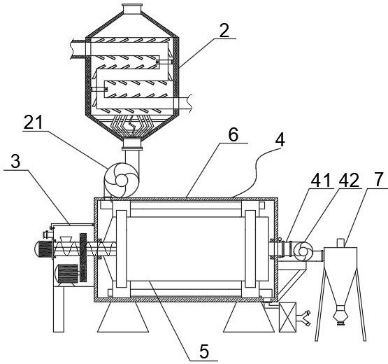
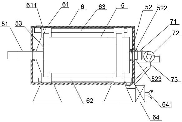
[0049] Such as figure 1 Shown: a material drying system that utilizes the waste heat of gas-fired boiler tail gas, including a drying mechanism 4, the drying mechanism 4 includes an outer heat preservation cylinder 6 and a rotating drying cylinder 5 arranged in the outer heat preservation cylinder 6 , the inner wall of the rotary drying drum 5 is provided with a lifting plate, and the outer thermal insulation drum 6 is ...
PUM
 Abstract
Description
Claims
Application Information