Power plant condensing system and process method

A technology for condensing systems and power plants, which is applied in steam engine installations, machines/engines, mechanical equipment, etc., can solve the problems of complex anti-corrosion and anti-scaling processes, large use of circulating water, and high waste water treatment costs, and achieve economic and environmental benefits. Significant, reduced equipment footprint, reduced equipment cost and footprint

Active Publication Date: 2021-11-19
JIANGNAN UNIV
View PDF8 Cites 1 Cited by
  • Summary
  • Abstract
  • Description
  • Claims
  • Application Information

AI Technical Summary

Problems solved by technology

[0006] In order to solve the above-mentioned technical problems, the present invention proposes a new steam condensing process method for steam turbines in power plants using carbon dioxide as the condensing medium. High cost, environmental pollution and other issues, and can reduce the carbon emissions of power plants to a certain extent, play the role of consumption reduction, energy saving, zero discharge of circulating wastewater

Method used


Image

  • Power plant condensing system and process method

Examples


Embodiment 1

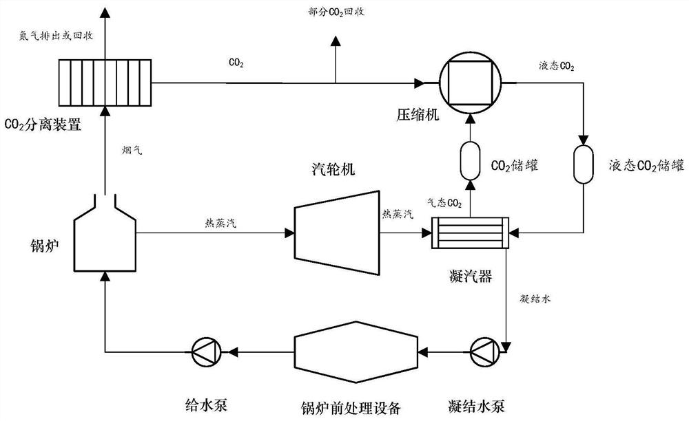
[0029] refer to figure 1 As shown, this embodiment provides a steam condensation system of a power plant, including: a steam turbine, a compressor, and a condenser, the steam turbine includes a steam turbine outlet, and the steam turbine outlet is used to discharge steam; the compressor includes a first compressor machine inlet, compressor outlet; the condenser includes a condenser steam inlet, a condenser medium inlet, a condenser drain, and a condenser outlet, the hot steam inlet is connected to the steam turbine outlet, and the The condenser medium inlet is connected to the compressor outlet, and the condenser medium inlet is used to input liquid carbon dioxide, and the condenser exhaust port is connected to the first compressor inlet; using liquid carbon dioxide as the cooling medium, the condenser In the condenser, it exchanges heat with the steam discharged from the steam turbine to condense the steam. The gasified carbon dioxide enters the compressor to be compressed in...

Embodiment 2

[0035] In this embodiment, the liquid carbon dioxide cooling medium is obtained by separating and compressing the boiler flue gas, continue to refer to figure 1 , on the basis of the system described in Embodiment 1, a boiler and a carbon dioxide separation device are also provided, the steam turbine also includes a steam turbine inlet, and the compressor also includes a second compressor inlet; the boiler includes a flue gas exhaust port and a hot steam outlet, the hot steam outlet is connected to the steam turbine inlet, and the flue gas exhaust port is used to discharge flue gas containing carbon dioxide, and the hot steam passes through the steam turbine through the steam turbine inlet and is discharged from the steam turbine outlet in the form of low-pressure steam; The carbon dioxide separation device includes a carbon dioxide separation inlet and a carbon dioxide separation outlet, the carbon dioxide separation inlet is connected to the flue gas exhaust port; the carbon ...


PUM


Abstract

The invention relates to a power plant condensing system and a process method. The power plant condensing system comprises a steam turbine, a compressor and a condenser, the steam turbine comprises a steam turbine outlet, and the steam turbine outlet is used for discharging low-pressure hot steam; the compressor comprises a first compressor inlet and a compressor outlet; and the condenser comprises a condenser hot steam inlet, a condenser medium inlet, a condenser water outlet and a condenser exhaust port, the hot steam inlet is connected with the steam turbine outlet, the compressor outlet is connected with the condenser medium inlet, the condenser medium inlet is used for inputting liquid carbon dioxide, and the condenser exhaust port is connected with the first compressor inlet . Carbon dioxide is used as a cooling medium, so that the problems of large use amount of circulating water of a power plant, complex corrosion and scale prevention process, high wastewater treatment cost, environmental pollution and the like can be fundamentally solved, and the effects of reducing consumption, saving energy and realizing zero discharge of circulating wastewater are achieved.

Description

technical field [0001] The invention relates to the technical field of energy saving and emission reduction of the circulating cooling system of a power plant, in particular to a steam condensation system and a process method of a power plant Background technique [0002] At present, the country has put forward the requirements of carbon emission reduction and zero discharge of wastewater from thermal power plants. The carbon emissions and wastewater discharge of coal-fired power plants mainly come from the following aspects: [0003] 1. Carbon emissions come from the flue gas discharge of power plant boilers. After desulfurization and denitrification, the main components of boiler flue gas are carbon dioxide, nitrogen and a small amount of water vapor. [0004] 2. The discharge of waste water from power plants mainly comes from the discharge of the circulating cooling water system. The mechanism of power generation is that the high-pressure steam from the boiler reaches the...

Claims


Application Information

Patent Timeline
Patent Type & Authority Applications(China)
IPC IPC(8): F01K11/02F01K9/00
CPCF01K11/02F01K9/003
Inventor 魏慧贤
Owner JIANGNAN UNIV
Why Eureka
Try Eureka