

High-conductivity electronic circuit capable of being rapidly printed at low temperature and preparation method and application thereof
An electronic circuit and high-conductivity technology, which is applied in the field of high-conductivity electronic circuits and their preparation, can solve the problems of affecting the conductivity of nano-technology particles, damage to temperature-sensitive substrates, and being unable to withstand high-temperature sintering, so as to improve the adhesion effect. , Broadening the scope of application, the effect of high applicability
- Summary
- Abstract
- Description
- Claims
- Application Information
AI Technical Summary
Problems solved by technology
Method used
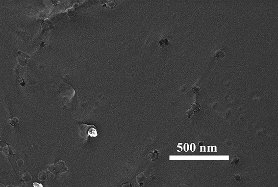
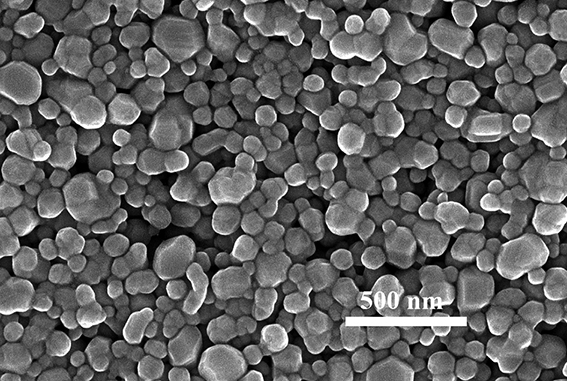
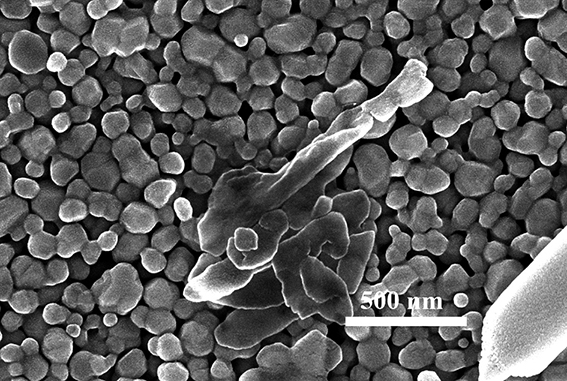
Image

Examples
Embodiment 1
[0025] A method for rapidly printing high-conductivity electronic circuits at low temperatures, comprising the following steps:
[0026] (1) Inkjet print nano-silver conductive ink on the surface of the PCB board, print patterned electronic circuits, and use low-temperature heat curing to dry the surface of nano-silver conductive ink; the low-temperature heat-curing temperature is 100 ℃, and the low-temperature heat-curing time 30 minutes;
[0027] (2) Inkjet print the micro-sintering solution on the surface of the printed nano-silver electronic circuit, and use a low-temperature thermosetting method to dry the surface. The low-temperature thermosetting temperature is 60 ℃, and the low-temperature thermosetting time is 10 minutes; the micro-sintering solution is propylene glycol Mixtures of methyl ether acetate, diethylene glycol diethyl ether and dipropylene glycol dimethyl ether;
[0028] (3) A gallium-based liquid alloy is used to coat the surface of the printed and micro-...
Embodiment 2
[0033] A method for rapidly printing high-conductivity electronic circuits at low temperatures, comprising the following steps:
[0034] (1) Inkjet print nano-gold conductive ink on the surface of bare PET, print patterned electronic circuits, and use infrared sintering to dry the surface of nano-gold conductive ink; the power of infrared sintering is 10 W, and the infrared sintering time is 5 minutes ;
[0035] (2) Inkjet print the micro-sintering solution on the surface of the printed nano-gold electronic circuit, and use infrared sintering to dry the surface. The power of infrared sintering is 50 W, and the infrared sintering time is 3 minutes; the micro-sintering solution is ethylene glycol Mixture of diethyl ether acetate and diethylene glycol diethyl ether;
[0036] (3) Use a gallium-based liquid alloy to coat the surface of the printed and micro-sintered nano-gold electronic circuit to obtain a high-conductivity electronic circuit with a resistance of 0.3Ω. The galliu...
Embodiment 3
[0040] A method for rapidly printing high-conductivity electronic circuits at low temperatures, comprising the following steps:
[0041] (1) Inkjet print nano-copper conductive ink on the surface of PI, print patterned electronic circuits, and use low-temperature heat curing to dry the surface of nano-copper conductive ink; the low-temperature heat-curing temperature is 60°C, and the low-temperature heat-curing time is 10min;
[0042] (2) Inkjet print the micro-sintering solution on the surface of the printed nano-copper electronic circuit, and use a low-temperature thermosetting method to dry the surface. The low-temperature thermosetting temperature is 100 ℃, and the low-temperature thermosetting time is 5 minutes; Mixtures of ethylene glycol diethyl ether, dipropylene glycol dimethyl ether and ethylene glycol dimethyl ether;
[0043] (3) Use a gallium-based liquid alloy to coat the surface of the printed and micro-sintered nano-copper electronic circuit to obtain a high-co...
PUM
| Property | Measurement | Unit |
|---|---|---|
| particle size | aaaaa | aaaaa |
| particle size | aaaaa | aaaaa |
| particle size | aaaaa | aaaaa |
Abstract
Description
Claims
Application Information