Photoelectric microorganism coupling nitrogen and carbon removal system
What is Al technical title?
Al technical title is built by PatSnap Al team. It summarizes the technical point description of the patent document.
A technology coupled with denitrification and microorganisms, applied in the field of photoelectric microbial coupling denitrification and carbon removal systems, can solve problems such as difficult to achieve treatment effects, and achieve good treatment effects
Active Publication Date: 2021-12-28
TIANJIN ENVIRONMENTAL PROTECTION TECHNICAL DEV CENT DESIGNING INST
View PDF5 Cites 1 Cited by
Summary
Abstract
Description
Claims
Application Information
AI Technical Summary
This helps you quickly interpret patents by identifying the three key elements:
Problems solved by technology
Method used
Benefits of technology
Problems solved by technology
Therefore, without adding additional carbon sources, it is difficult to achieve a good treatment effect on refractory water bodies with low and medium concentrations and imbalanced carbon-nitrogen ratios.
Method used
Image
Click on the blue label to locate the original text in one second.
Reading with bidirectional positioning of images and text.
Examples
Embodiment 1
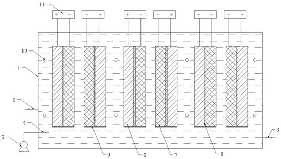
[0037] A photoelectric microbial coupling denitrification and carbon removal system, including a housing 1, an aeration head 4, a blower 5, a processing unit, an ultraviolet lamp 10 and a power supply 11;
[0038] The processing unit is arranged inside the housing 1, and there is a space between the processing unit and the bottom of the housing 1. The space below the processing unit is provided with an aeration head 4, and the aeration head 4 is connected to the blower 5 through a connecting pipe; the housing 1 The water inlet pipe 2 and the water outlet pipe 3 are also arranged on the top, and the bracket 9 for supporting the processing unit is arranged inside the housing 1;
[0039] The processing unit is a flat layered structure, including a modified photoelectrode plate 6, a biocathode layer 7, and a particle electrode layer 8 sandwiched between the modified photoelectrode plate 6 and the biocathode layer 7. The modified photoelectrode plate 6 and The positive pole of the ...
Embodiment 2
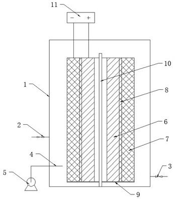
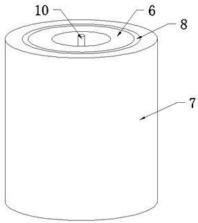
[0048] On the basis of the above-mentioned embodiment, the processing unit is provided with one, which is a cylindrical layered structure, and from the center of the circle to the outside is a modified photoelectrode plate 6, a particle electrode layer 8 and a biological cathode layer 7, and the ultraviolet lamp 10 is arranged on At the center of the circle, there is a space between the ultraviolet lamp 10 and the modified photoelectrode plate 6 .
[0049] Wherein, the preparation method of the modified photoelectrode is: using 60°C water bath electrodeposition to prepare Cu 2 O thin film, and use chemical deposition to modify a layer of CuI on its surface.
[0050] The biocathode layer 7 is based on a wax-impregnated graphite electrode, and polyaniline is prepared in aniline sulfate solution by cyclic voltammetry, and finally a polyaniline-microbial membrane composite cathode is produced through the strengthening effect of an external electric field.
[0051] Preparation of ...
PUM
Abstract
The invention provides a photoelectric microorganism coupling nitrogen and carbon removal system which comprises a treatment unit, wherein the treatment unit comprises a modified photoelectric electrode plate, a biological cathode layer and a particle electrode layer clamped between the modified photoelectric electrode plate and the biological cathode layer, the modified photoelectric electrode plate is connected with a positive electrode of a power supply, the biological cathode layer is connected with a negative electrode of the power supply, and an ultraviolet lamp is arranged opposite to the modified photoelectric electrode plate; the particle electrode layer and the biological cathode layer are both inoculated with microbial denitrifying bacteria, the modified photoelectric electrode plate generates electron-hole pairs under the excitation of ultraviolet light, holes are used for removing carbon, and photo-generated electrons are transferred to the denitrifying bacteria of polyurethane foam for denitrification and nitrogen removal of microorganisms; and meanwhile, the modified photoelectric electrode plate and the biological cathode layer are connected with the power supply to form electrolysis, and electrons generated by electrolysis are transferred to the biological cathode layer to perform microbial denitrification nitrogen removal. According to the invention, the modified photoelectrode is introduced into a microbial electrochemical system and is coupled with a denitrification biological cathode, so that a photocatalytic biological membrane electrode technology is constructed, and nitrogen and carbon are synchronously removed.
Description
technical field [0001] The invention relates to the field of wastewater treatment, in particular to a photoelectric microbial coupling denitrification and carbon removal system. Background technique [0002] The existing optical-electrical-biological coupling needs to be carried out in three pools, and the project cost is large and the cost is high. The denitrifying bacteria for denitrification and nitrogen removal are heterotrophic microorganisms, and the organic carbon source is required to participate in providing reaction electrons for the denitrification reaction. In order to realize the true biological denitrification, there must be enough carbon source organic matter. Therefore, without adding additional carbon sources, it is difficult to achieve a good treatment effect on refractory water bodies with low-to-medium concentrations and imbalanced carbon-nitrogen ratios. Contents of the invention [0003] In view of this, the present invention aims to propose a photoe...
Claims
Application Information
Patent Timeline
Application Date:The date an application was filed.
Publication Date:The date a patent or application was officially published.
First Publication Date:The earliest publication date of a patent with the same application number.
Issue Date:Publication date of the patent grant document.
PCT Entry Date:The Entry date of PCT National Phase.
Estimated Expiry Date:The statutory expiry date of a patent right according to the Patent Law, and it is the longest term of protection that the patent right can achieve without the termination of the patent right due to other reasons(Term extension factor has been taken into account ).
Invalid Date:Actual expiry date is based on effective date or publication date of legal transaction data of invalid patent.