
Spiral air ceramic nozzle of coal-fired boiler and preparation method thereof
A ceramic nozzle and coal-fired boiler technology, applied in the field of boiler combustion, can solve the problems of a large total base of soot and other emissions, insufficient coal combustion, insufficient oxygen supply, etc., so as to improve the utilization rate of waste residue and reduce the difficulty of treatment. , the effect of improving heat resistance
- Summary
- Abstract
- Description
- Claims
- Application Information
AI Technical Summary
Problems solved by technology
Method used
Image

Examples
Embodiment 1
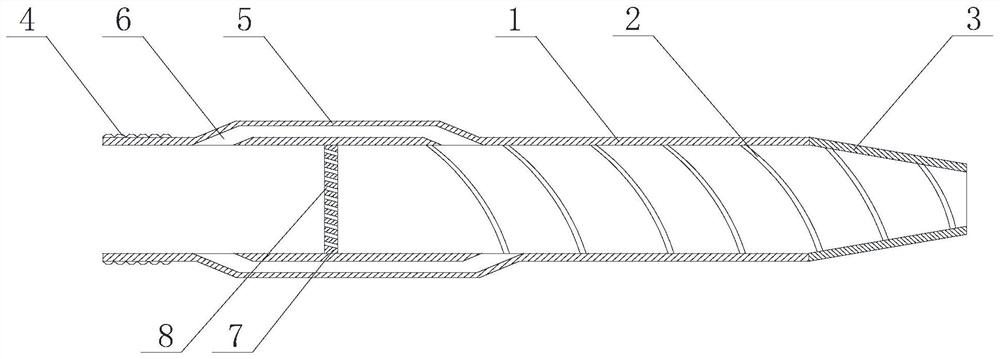
[0068] Such as figure 1 and figure 2 The shown spiral air ceramic nozzle for a coal-fired boiler includes a main body 1 , and a spiral groove 2 is arranged inside the main body 1 , and the spiral groove 2 extends in a spiral shape on the inner wall of the main body 1 .
[0069] In this embodiment, through the structural design of the spiral groove, the air flow forms a cyclone in the main body, and then a spiral wind is ejected from the air outlet. The spiral groove is a groove arranged on the inner wall of the main body. The extension direction of the groove is the extension direction of the helix on the inner wall. Rotation is generated during the process, and finally the purpose of spraying spiral wind is achieved.
[0070] In one or more embodiments, the spiral groove can extend along the entire inner wall of the main body, or along a part of the inner wall of the main body. In one or more embodiments, the helical groove can be a continuous helical groove, or can be co...
Embodiment 2
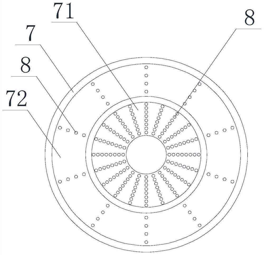
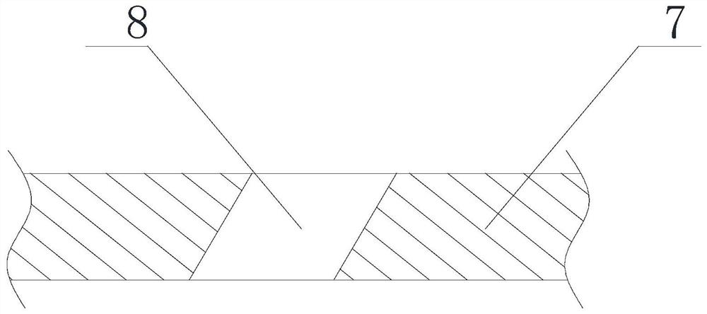
[0073] On the basis of Example 1, such as Figure 1 to Figure 5 As shown, the main body 1 is provided with a partition 7, and the partition 7 divides the internal space of the main body 1 into an air inlet area connected to the air inlet end and a cyclone area connected to the air outlet end. The chamfered hole 8 in the air intake area and the cyclone area has an included angle between the central axis of the chamfered hole 8 and the central axis of the partition plate 7 .
[0074] In some embodiments, such as image 3 As shown, the angle between the central axis of the chamfered hole and the central axis of the separator is 30-70°. Preferably, the included angle is 45-60°.
[0075] Preferably, in one or more embodiments, as figure 2 As shown, the separator 7 is provided with an inner ring area 71 and an outer ring area 72 located outside the inner ring area 71, and the chamfered holes 8 are arranged in the inner ring area 71 and the outer ring area 72, The number of cham...
Embodiment 3
[0079] On the basis of the above examples, if Figure 1 to Figure 5 As shown, the main body 1 is also provided with at least one swirl-assist tube 5, the inside of the swirl-assist tube 5 forms a swirl-assist air passage 6, and one end of the swirl-assist air passage 6 communicates with the air intake area, The other end of the air duct 6 communicates with the cyclone area.
[0080] The two ends of the swirl-assisted air passage are connected to the air intake area and the cyclone area respectively, so that a small part of the gas in the intake area enters the swirl-assisted tube before it contacts the partition, and then passes through the connection between the swirl-assisted air passage and the cyclone area The mouth returns to the main body. Since the incident direction of the returning swirl-promoting airflow is inconsistent with the flow direction of the airflow in the cyclone area, it acts as a bias, impacts the main airflow and causes the main airflow to rotate to a c...
PUM
| Property | Measurement | Unit |
|---|---|---|
| thermal resistance | aaaaa | aaaaa |
Abstract
Description
Claims
Application Information