
Dual-refrigeration cycle methane washing synthesis gas cryogenic separation device and separation method

A separation device and synthesis gas technology, applied in the field of gas cryogenic separation, can solve the problems of high energy consumption of methane washing process, low CO recovery rate, high equipment investment, etc. Moderate effect

Pending Publication Date: 2021-12-31
BEIJING PETROCHEM ENG
View PDF9 Cites 0 Cited by
  • Summary
  • Abstract
  • Description
  • Claims
  • Application Information

AI Technical Summary

Problems solved by technology

[0017] Since the raw material synthesis gas contains more CH 4 and N 2 , the existing partial condensation or methane washing process of conventional cryogenic separation has high energy consumption, and high-pressure nitrogen or high-pressure carbon monoxide cycle refrigeration is required, but the amount of circulating gas is often large, so the energy consumption is also high, and the downstream device has a high impact on the product. When the carbon monoxide purity requirement is high, pressure swing adsorption and membrane separation can no longer meet the requirements. At this time, the cryogenic separation device often causes a very high investment in driving equipment due to the large circulation of refrigeration gas.
In addition, due to the influence of impurities, the recovery rate of CO is often not high, and only the content of CO is higher than that of H 2 The recovery rate of CO in the raw material synthesis gas is relatively high. Taking dry coal gasification as an example, the recovery rate of CO in the partial condensation process can usually reach about 90% (while the raw material with H2 component content in the raw gas is higher than the CO component The recovery rate of CO in syngas is usually about 80%. If it is to be increased to 90%, more energy consumption needs to be paid; conventional methane washing process CO can achieve 90% recovery rate, but the treatment of the above-mentioned CH 4 and N 2 More components, often the energy consumption of conventional methane washing process is higher

Method used


Image

  • Dual-refrigeration cycle methane washing synthesis gas cryogenic separation device and separation method
  • Dual-refrigeration cycle methane washing synthesis gas cryogenic separation device and separation method
  • Dual-refrigeration cycle methane washing synthesis gas cryogenic separation device and separation method

Examples


Embodiment 1

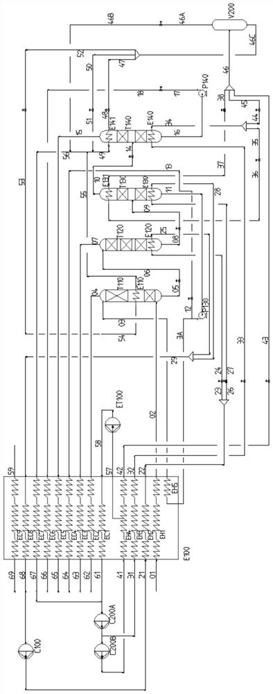
[0076] This embodiment provides a methane and nitrogen double refrigeration cycle methane washing synthesis gas cryogenic separation device. The structure of the separation device is as figure 1 As shown, it includes methane scrubber T110, flash tower T120, first separation tower T130, second separation tower T140, first cycle refrigeration system, second cycle refrigeration system, methane pump P130, carbon monoxide pump P140, main heat exchanger E100 and cold box.

[0077] The methane scrubber T110 is used for the preliminary separation of hydrogen in the synthesis gas, avoiding the problems of lower tower top temperature and higher energy consumption caused by high hydrogen content in the synthesis gas, and is conducive to maintaining the stability of the tower top of the subsequent separation tower.

[0078] The flash tower T120 is used to further perform gas-liquid mass transfer in the liquid-phase syngas treated by the methane scrubber T110 to realize the separation of ...

Embodiment 2

[0101] This embodiment provides a methane and nitrogen double refrigeration cycle methane washing synthesis gas cryogenic separation method, which is carried out in the separation device of embodiment 1. Such as figure 1 As shown, the method includes the following steps:

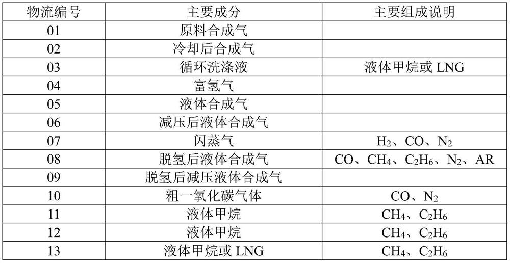
[0102] The raw synthesis gas (stream 01) of about 3.5 MPaG is cooled by the hot stream channel EH1 and then converted into stream 02 and sent to the gas inlet of the methane scrubber T110 tower. The synthesis gas is subjected to gas-liquid separation at the bottom of the methane scrubber T110 to obtain liquid-phase synthesis gas (stream 05) and rising gas. The ascending gas is exchanged with the liquid methane as the circulating scrubbing liquid in the top reflux system, the non-hydrogen gas in the ascending gas is absorbed by the liquid methane, and the unabsorbed gas forms hydrogen-rich gas (stream 04) from the gas outlet at the top of the tower Discharged and then reheated by the cold stream channel EC2...

Embodiment 3

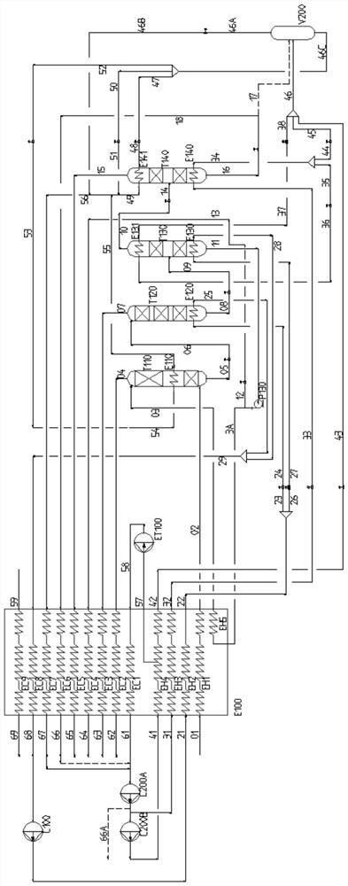
[0119] This embodiment provides a methane and carbon monoxide dual refrigeration cycle methane washing synthesis gas cryogenic separation device. The structure of this separation device is similar to the structure of the separation device provided in Example 1, and the main difference is that the separation device of this embodiment does not contain a carbon monoxide pump P140; the liquid outlet of the second separation tower T140 can be connected with the inlet of the gas-liquid separation tank V200 on the one hand. On the other hand, it can communicate with the inlet of the first-stage compressor C200A in the second cycle refrigeration system through the cold flow channel EC6; the outlet of the first-stage compressor C200A can directly communicate with the CO product pipeline network.

[0120] Specifically, the structure of the separation device provided in this embodiment is as follows figure 2 As shown, including methane scrubber T110, flash tower T120, first separation t...


PUM


Abstract

The invention provides a dual-refrigeration cycle methane washing synthesis gas cryogenic separation device and a separation method. The separation device comprises a methane washing tower, a flash tower, a first separation tower, a second separation tower, a first circulating refrigeration system and a second circulating refrigeration system, wherein the methane washing tower, the flash tower, the first separating tower and the second separating tower are sequentially communicated, the first circulating refrigerating system comprises a methane circulating refrigerating system, and the second circulating refrigerating system comprises a nitrogen circulating refrigerating system or a carbon monoxide circulating refrigerating system. The invention also provides a separation method which is carried out in the separation device. According to the method, the synthesis gas with high methane content and nitrogen content can be efficiently separated, a hydrogen-rich product, a pure methane product and a pure carbon monoxide product are prepared at the same time, and the relatively high carbon monoxide recovery rate is ensured while the energy consumption is greatly reduced.

Description

technical field [0001] The invention relates to the technical field of gas cryogenic separation, in particular to a double refrigeration cycle methane washing synthesis gas cryogenic separation device and separation method. Background technique [0002] At present, it is widely used in syngas (containing H 2 , CO, CH 4 , C2H6, N 2 , AR and other components) cryogenic separation is liquid nitrogen washing, partial condensation process, methane washing process, and carbon monoxide washing derived from methane washing. Partial condensation process, methane scrubbing process or carbon monoxide scrubbing process are often used in the process. [0003] When the chemical synthesis unit needs a large amount of high-purity carbon monoxide products, and at this time the raw material synthesis gas contains higher methane / nitrogen components (such as CH 4 >7v%, N 2 >4v%), neither pressure swing adsorption nor membrane separation should be used. When the scale of carbon monoxi...

Claims


Application Information

Patent Timeline
Patent Type & Authority Applications(China)
IPC IPC(8): C10L3/10B01D53/18F25B1/10F25B29/00F25B41/30
CPCC10L3/10B01D53/18F25B1/10F25B29/003F25B41/30
Inventor 孙彦泽董永强樊义龙慕韩锋肖超黄金库卞潮渊
Owner BEIJING PETROCHEM ENG
Learn More