
Four-path orthogonal signal generator based on E-type resonators
A quadrature signal and resonator technology, applied in the field of four-way quadrature signal generator, can solve the problems of complex design structure, large amplitude difference, large size, etc., and achieve the effect of low production cost, small phase deviation and simple structure
- Summary
- Abstract
- Description
- Claims
- Application Information
AI Technical Summary
Problems solved by technology
Method used
Image

Examples
Embodiment 1
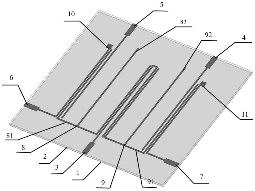
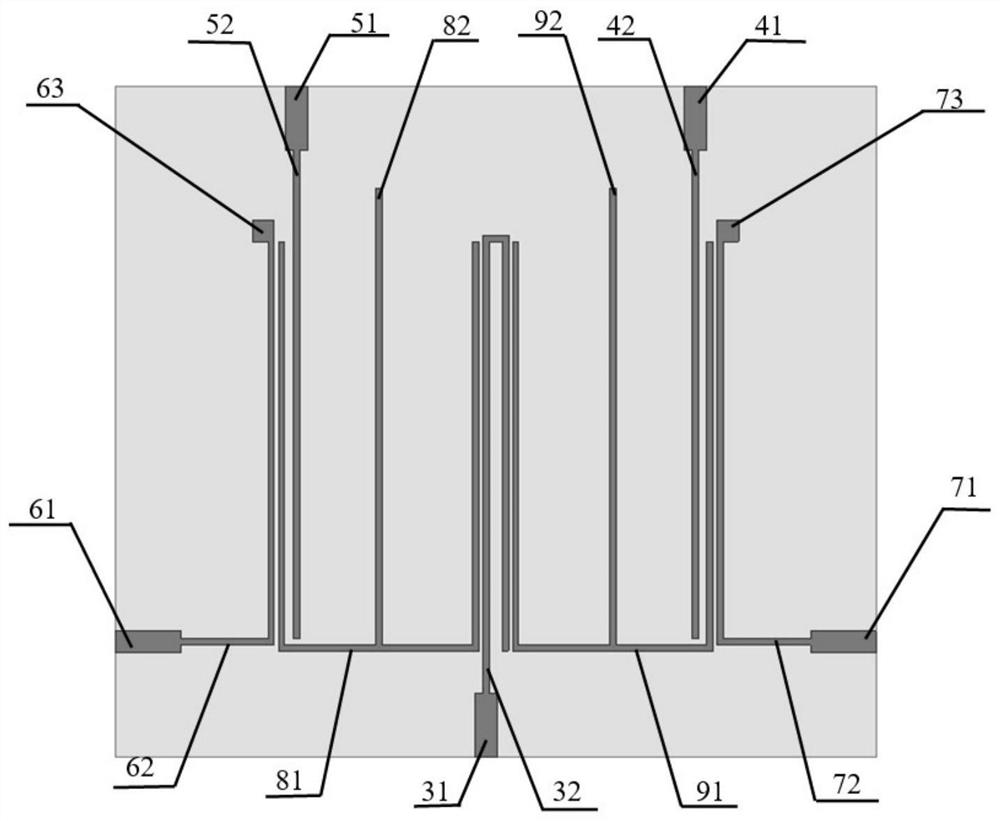
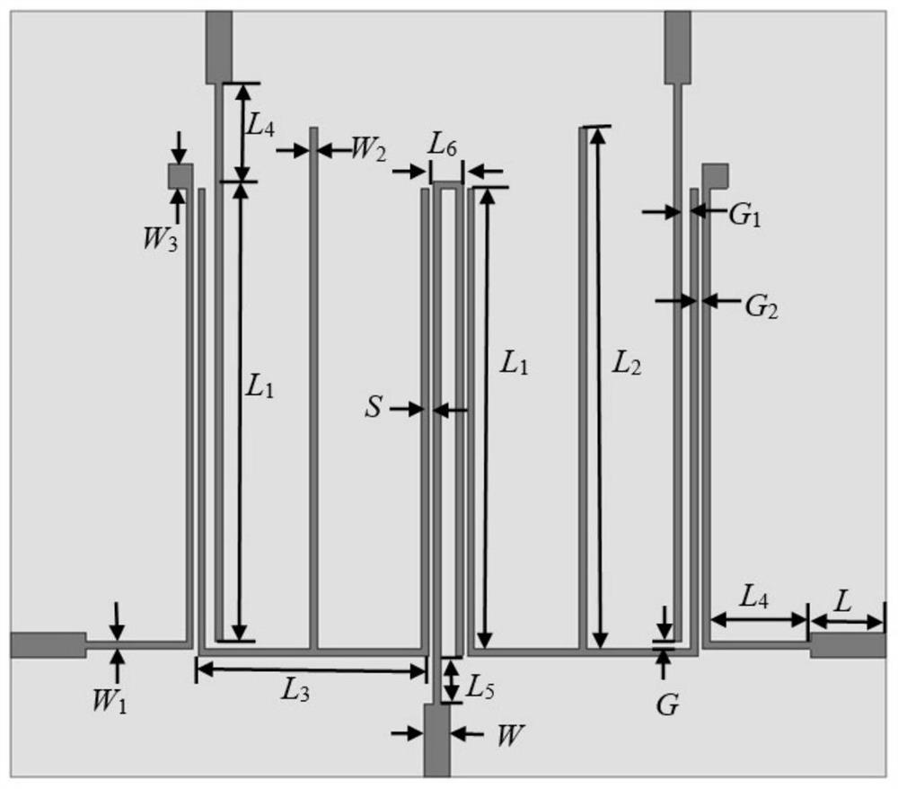
[0033] The structure diagram of the four-way quadrature signal generator based on the E-type resonator is as follows: figure 1 As shown, the top view is as figure 2 As shown, the relevant dimensions and specifications are as follows image 3 shown. The dielectric plate 2 used has a relative permittivity of 3.55, a thickness of 0.508 mm, and a loss tangent of 0.0027. to combine image 3 , the size parameters of the four-way quadrature signal generator are as follows: W=1.18mm, L=3mm, W 1 = 0.31mm, W 2 = 0.23mm, W 3 = 1 mm, L 1 =19.2mm,L 2 =22.1mm,L 3 =9.2mm,L 4 = 4mm, L 5 = 2mm, L 6 =1.2mm, S=0.18mm, G=0.3mm, G 1 = 0.42mm, G 2 = 0.21 mm. The overall total area of the four quadrature signal generators is 31.81×35mm 2 .
[0034] The quadrature signal generator of this example is modeled and simulated in the electromagnetic simulation software HFSS.15. Figure 4 It is the S-parameter simulation diagram of the four-way orthogonal signal generator in this example...
PUM
 Abstract
Description
Claims
Application Information