
Chain grate-rotary kiln denitration system

A rotary kiln and chain grate technology, applied in the field of rotary kiln denitrification, can solve the problems of reducing the spiral rotation rate of flue gas of a cyclone dust collector, weakening the dust removal effect of the cyclone dust collector, reducing the centrifugal force of dust particles, etc. The effect of improving the practical application effect and improving the dust removal efficiency

Pending Publication Date: 2022-01-28
杨 志彬
View PDF5 Cites 3 Cited by
  • Summary
  • Abstract
  • Description
  • Claims
  • Application Information

AI Technical Summary

Problems solved by technology

[0003] For example, a Chinese patent with the application number CN201810381207.6 discloses a high-efficiency multi-tube cyclone dust collector. This technical solution uses multiple sets of parallel cyclones to separate the ash particles in the flue gas to the flue gas under the action of centrifugal force. The outer layer of the flow and sinks downward, and the purified flue gas from which the dust particles have been separated rotates along the axis of the cyclone to rise and discharge, and is discharged through the smoke exhaust pipe, which improves the dust removal efficiency of the device; The parallel cyclone will block the flow of flue gas in the cyclone dust collector, thereby reducing the spiral rotation speed of the flue gas inside the cyclone dust collector, reducing the centrifugal force on the dust particles in the flue gas, and weakening the dust removal effect of the cyclone dust collector , resulting in the limitation of the technical solution

Method used


Image

  • Chain grate-rotary kiln denitration system
  • Chain grate-rotary kiln denitration system
  • Chain grate-rotary kiln denitration system

Examples


Embodiment Construction

[0025] In order to make the technical means, creative features, goals and effects achieved by the present invention easy to understand, the present invention will be further described below in conjunction with specific embodiments.

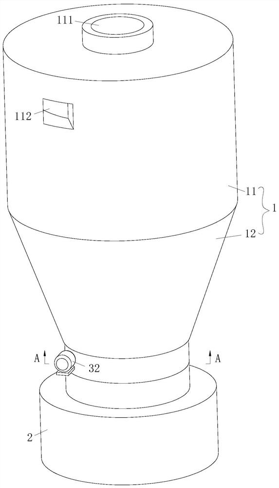
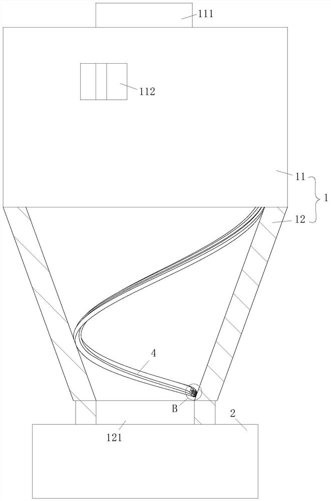
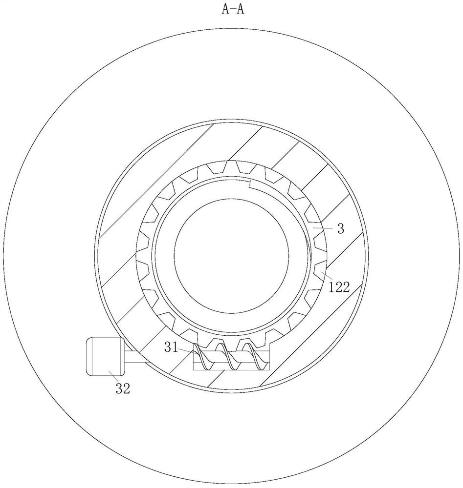
[0026] Such as Figure 1 to Figure 4 As shown, a grate-rotary kiln denitrification system according to the present invention includes a cyclone dust collector; the cyclone dust collector also includes a body 1, a dust collection box 2 and a controller; the body 1 includes a cylinder 11 and the cone 12; the cylinder 11 and the cone 12 are fixedly connected, the upper end of the cylinder 11 is provided with an exhaust port 111, and the inner wall of the cylinder 11 is provided with an air inlet 112; between the cone 12 and the dust box 2 The space is connected through the dust outlet 121; the inner wall of the cone 12 is provided with a mounting groove 122, and the gear 3 is rotatably connected in the mounting groove 122; the inner wall of the cone ...


PUM


Abstract

The invention belongs to the technical field of rotary kiln denitration, and particularly relates to a chain grate-rotary kiln denitration system which comprises a cyclone dust collector. The cyclone dust collector further comprises a machine body, a dust collecting box and a controller; the machine body comprises a cylinder and a cone; the cylinder is fixedly connected with the cone, an exhaust port is formed in the upper end of the cylinder, and an air inlet is formed in the inner wall of the cylinder; a scraping plate is arranged, the scraping plate can scrape off dust accumulated on the inner wall of the cone and prevent the dust from being accumulated on the inner wall of the cone, on one hand, the dust is prevented from blocking the dust discharging opening, on the other hand, the dust accumulated on the inner wall of the cone is prevented from being rolled up by airflow, and therefore the dust removal effect is improved; and rotation of the scraping plate not only increases the flow rate of airflow in the cyclone dust collector, increases the centrifugal force on dust particles and accelerates the separation of dust, but also plays a role in guiding smoke entering through the air inlet and accelerates the entering of the smoke, so that the dust collection efficiency of the cyclone dust collector is improved, and the practicability of the cyclone dust collector is further improved.

Description

technical field [0001] The invention belongs to the technical field of denitrification of a rotary kiln, and in particular relates to a chain grate-rotary kiln denitrification system. Background technique [0002] my country's pellet production is mainly based on the grate machine-rotary kiln process, using the grate machine to dry, preheat the raw pellets, consolidate and roast the pellets in the rotary kiln, cool the finished pellets on the ring cooler, and use the grate machine-rotary kiln balls A large amount of flue gas will be produced during the combustion of the pellet production process, and the flue gas has a high content of nitrogen oxides. If the nitrogen oxides are directly discharged into the atmosphere, it will cause environmental pollution and affect the ecology and human health. Therefore, before discharging , it is necessary to denitrate the flue gas produced by the grate machine-rotary kiln pellet production, and the flue gas after the denitrification treatm...

Claims


Application Information

Patent Timeline
Patent Type & Authority Applications(China)
IPC IPC(8): B01D45/14B01D45/18
CPCB01D45/14B01D45/18
Inventor 杨志彬李海洋
Owner 杨 志彬
Learn More