A petrochemical industry flue gas denitrification device and its use method

A flue gas and denitration technology, which is applied in chemical instruments and methods, separation methods, dispersed particle separation, etc., can solve the problems of short service life of catalysts, high operating costs, affecting denitration efficiency, etc., to improve the mixing uniformity and temperature. Balanced degree and effect of improving denitrification efficiency

Active Publication Date: 2022-03-08
山东东源新材料科技有限公司
View PDF3 Cites 0 Cited by
  • Summary
  • Abstract
  • Description
  • Claims
  • Application Information

AI Technical Summary

Problems solved by technology

SNCR technology has low investment, low operating cost, simple system and wide application range, but its denitrification efficiency is low, only 30%-50%, far from meeting the emission standards. SCR technology has high denitrification efficiency, which can reach more than 95%, but Its denitrification efficiency is limited by the activity of the catalyst. When the SCR equipment is used alone, the service life of the catalyst is short and the operating cost is high.
In addition, when using SCR technology, the uniformity of flue gas and ammonia as a reducing agent directly affects the reduction degree of nitrogen oxides in flue gas. The current denitrification mixing device only passes flue gas and ammonia together. into the mixing chamber, after simple mixing, it is passed into the SCR reactor for denitrification, so that the mixing uniformity of flue gas and ammonia gas is low, which affects the denitrification efficiency

Method used


Image

  • A petrochemical industry flue gas denitrification device and its use method
  • A petrochemical industry flue gas denitrification device and its use method
  • A petrochemical industry flue gas denitrification device and its use method

Examples


specific Embodiment approach

[0050] It should be noted that the structures, proportions, sizes, etc. shown in the drawings attached to this specification are only used to match the content disclosed in the specification, for those who are familiar with this technology to understand and read, and are not used to limit the implementation of the present invention Any modification of structure, change of proportional relationship or adjustment of size shall fall within the range covered by the technical content disclosed in the present invention without affecting the effect and purpose of the present invention. within range.

[0051] At the same time, terms such as "upper", "lower", "left", "right", "middle" and "one" quoted in this specification are only for the convenience of description and are not used to limit this specification. The practicable scope of the invention and the change or adjustment of its relative relationship shall also be regarded as the practicable scope of the present invention without...

Embodiment 1

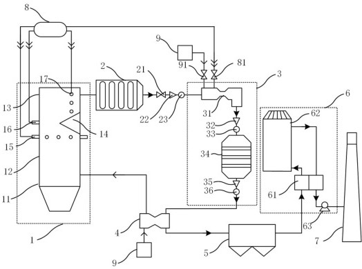
[0053] combined with figure 1 In this embodiment, a petrochemical industry flue gas denitrification device is provided, including SNCR reaction unit 1, waste heat boiler 2, SCR reaction unit 3, air preheater 4, electrostatic precipitator 5, and desulfurization unit sequentially connected along the flue gas direction 6 and a chimney 7; the SNCR reaction unit 1 includes a boiler 11 and a spray gun arranged on the boiler 11, and the spray gun communicates with the ammonia gas source 8 and the air source 9 respectively, and the SCR reaction unit 3 includes a boiler located on the flue The mixing device 31 in the horizontal section and the SCR reactor 34 located in the vertical section of the flue, the SCR reactor 34 is filled with a molecular sieve catalyst with double active centers, and the mixing device 31 communicates with the ammonia gas source 8 and the air source respectively 9. The desulfurization unit 6 includes a desulfurization tower 62 .

[0054] In the above technica...

Embodiment 2

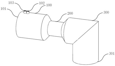
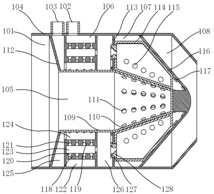
[0060] combined with Figures 2 to 6 , the present embodiment provides a mixing device 31 used in Embodiment 1, the mixing device 31 includes a mixing pipe section 100, a thin diameter pipe section 200 and a diversion pipe section 300 connected in sequence, and flue gas and diluted ammonia gas are mixed in the mixing pipe section After mixing in 100, it is homogenized in the narrow-diameter pipe section 200, and then flows out after being vertically guided by the guide pipe section 300.

[0061] The specific structure is as figure 2 As shown, the mixing tube section 100 and the thin-diameter tube section 200 are horizontal tubes, the mixing tube section 100 is horizontally provided with a flue gas inlet 101, and is vertically provided with an ammonia gas inlet 102 and an air inlet 103, and the mixing tube section 100 The tail is tapered and connected to the thin-diameter pipe section 200, the diversion pipe section 300 is a right-angle pipe, the horizontal end of which is ta...


PUM


Abstract

The present invention relates to the technical field of flue gas treatment, in particular to a flue gas denitrification device in the petrochemical industry and its use method. The flue gas denitrification device includes an SNCR reaction unit, a waste heat boiler, an SCR reaction unit, and an air preheater sequentially connected along the flue gas direction. , an electric dust collector, a desulfurization unit and a chimney; the SNCR reaction unit includes a boiler and a spray gun arranged on the boiler, and the spray gun is respectively communicated with an ammonia source and an air source, and the SCR reaction unit includes a boiler located at the flue level The mixing device of the section and the SCR reactor arranged in the vertical section of the flue, the molecular sieve catalyst with double active centers is filled in the SCR reactor, the mixing device is respectively connected to the ammonia source and the air source, and the desulfurization unit includes Desulfurization tower. The invention adopts SNCR and SCR technologies to combine denitrification, uses a catalyst with double active centers for catalysis, and uses a high-efficiency mixing device for ammonia supplementation, so the denitrification efficiency is high and the denitrification operation cost is low.

Description

technical field [0001] The invention relates to the technical field of flue gas treatment, in particular to a petrochemical industry flue gas denitrification device and a method for using the same. Background technique [0002] Nitrogen oxides, as one of the main air pollutants, are the targets of the country's strict emission control after sulfur dioxide. Coal-fired boilers are the largest source of nitrogen oxide emissions in the petrochemical industry. The nitrogen oxides emitted by coal-fired boilers in the petrochemical industry account for 60-70% of my country's total nitrogen oxide emissions. It is of great significance to reduce oxide pollution and achieve sustainable development. [0003] The most widely used flue gas denitrification technologies are SCR technology and SNCR technology. SNCR technology has low investment, low operating cost, simple system and wide application range, but its denitrification efficiency is low, only 30%-50%, far from meeting the emissi...

Claims


Application Information

Patent Timeline
Patent Type & Authority Patents(China)
IPC IPC(8): B01D53/56B01D53/86B01D53/34
CPCB01D53/56B01D53/8631B01D53/343B01D53/346B01D2251/2062
Inventor 葛成敏陈浩赵秀萍朱晓鹏
Owner 山东东源新材料科技有限公司
Why Eureka
Try Eureka