
Double-bed sludge drying incineration system and incineration method

A sludge drying and sludge technology, applied in combustion methods, dehydration/drying/thickened sludge treatment, incinerators, etc., can solve the problems of limited drying production capacity, low heat transfer coefficient of rotary kiln and moving bed, etc. Achieve the effect of high drying strength, improved drying production capacity, and large processing capacity

Pending Publication Date: 2022-01-28
北京华能长江环保科技研究院有限公司 +1
View PDF0 Cites 0 Cited by
  • Summary
  • Abstract
  • Description
  • Claims
  • Application Information

AI Technical Summary

Problems solved by technology

[0004] Sludge drying equipment has rotary kiln, moving bed, fluidized bed and air flow bed etc. Rotary kiln and moving bed have low heat transfer coefficient and limited drying capacity

Method used


Image

  • Double-bed sludge drying incineration system and incineration method

Examples


Embodiment 1

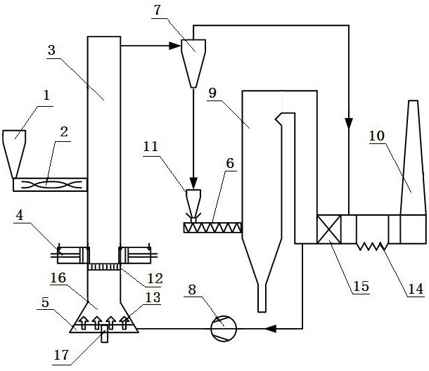
[0018] A double-bed sludge drying and incineration system, which consists of: a wet sludge bin 1, the bottom of the wet sludge bin is connected to a plunger pump 2, and the plunger pump is connected to an air flow bed 3, the The top of the entrained entrained bed is connected with the separator 7, the lower part of the plunger pump in the entrained entrained bed is equipped with a grate 12, the two sides above the grate are respectively equipped with a crusher 4, and the bottom of the entrained entrained bed is equipped with a fluidized bed 16. There is an air chamber 5 below the fluidized bed, an air cap 13 is installed on the upper part of the air chamber, and a slag discharge port 17 is installed at the bottom of the air chamber. The air chamber is connected to the boiler 9 through the induced draft fan 8, The top of the separator is connected to the front end of the dust collector 14, the bottom of the separator is connected to the dry sludge bin 11, the dry sludge bin is c...

Embodiment 2

[0020] According to the double-bed sludge drying and incineration system described in Embodiment 1, the air preheater 15 and the dust collector are installed in sequence at the tail of the boiler, and the dust collector is connected to the chimney 10, and the dust collector is connected to the chimney 10. The induced draft fan is arranged between the front end of the air preheater and the air chamber.

Embodiment 3

[0022] According to the double-bed sludge drying and incineration system described in Example 1, the grate is installed in the lower part of the air-flow bed as a grid structure with a grid distance of 15mm, and extrusion crushers are arranged on both sides of the upper plane of the grate , the structure of the hood is a bell type, the hood has an inner hole of the core tube and an outer hole of the outer cover, and the fluidization wind speed at the bottom of the entrained flow bed is 2~4m / s.


PUM


Abstract

The invention discloses a double-bed sludge drying incineration system and an incineration method. A rotary kiln and a moving bed are adopted in a sludge drying device in the prior art, the heat transfer coefficient is low, and the drying production capacity is limited. The system includes a wet sludge bin (1), the bottom of the wet sludge bin is connected with a plunger pump (2); the plunger pump is connected with an entrained-flow bed (3); the top of the entrained-flow bed is connected with a separator (7); a grate (12) is mounted at the lower part of the plunger pump in the entrained-flow bed. Crushers (4) are installed on the two sides above the grate respectively, a fluidized bed (16) is installed at the bottom of the entrained-flow bed, an air chamber (5) is arranged below the fluidized bed, and an air cap (13) is installed on the upper portion of the air chamber, the bottom of the air chamber is provided with a slag discharge port (17), the air chamber is connected with a boiler (9) through an induced draft fan (8), the top of the separator is connected to the front end of a dust remover (14), the bottom of the separator is connected with a dry sludge bin (11), the dry sludge bin is connected with a feeder (6), and the feeder is communicated with the boiler. The incineration system is used for the double-bed sludge drying incineration system.

Description

technical field [0001] The invention relates to the technical field of energy saving and environmental protection, in particular to a double-bed sludge drying and incineration system and an incineration method. Background technique [0002] With the acceleration of my country's urbanization process and the improvement of people's living standards, the amount of urban domestic sewage has increased sharply, and the amount of sludge generated has increased sharply, causing serious environmental pollution. According to statistics, in 2015, the amount of sludge with a moisture content of 80% in my country has reached 3359 10,000 tons, and still has an annual growth rate of about 11%, and the sludge production will reach 60 million tons by the end of 2020; [0003] Traditional sludge treatment methods include stable landfill, composting, sea reclamation, and incineration. Sludge incineration is the most "thorough" sludge treatment method. Compared with other sludge treatment techno...

Claims


Application Information

Patent Timeline
Patent Type & Authority Applications(China)
IPC IPC(8): F23G7/00F23G5/033F23G5/04F23G5/30F23G5/44F23G5/46F23J15/02F23L15/00C02F11/13
CPCF23G7/001F23G5/006F23G5/04F23G5/033F23G5/30F23G5/44F23G5/46F23J15/022F23L15/00C02F11/13F23G2201/10F23G2201/80F23G2203/503F23G2206/203F23G2209/12Y02E20/12Y02E20/34
Inventor 李昱喆袁野郭磊李楠李斌张军华吉明锴李新琴
Owner 北京华能长江环保科技研究院有限公司
Learn More