
Magnetic fluid filled optical fiber magnetic field and displacement sensor

A displacement sensor and magnetic fluid technology, which is applied to the use of magneto-optical equipment for magnetic field measurement, the size/direction of the magnetic field, the direction of the instrument, etc., can solve the problems of complex structure, the dislocation welding structure of the sensing unit is not easy to operate, etc., and achieves a small volume. , to achieve real-time monitoring and measurement, to avoid the effect of temperature interference

Pending Publication Date: 2022-03-04
HARBIN UNIV OF SCI & TECH
View PDF0 Cites 0 Cited by
  • Summary
  • Abstract
  • Description
  • Claims
  • Application Information

AI Technical Summary

Problems solved by technology

For example: In 2018, Zhang et al. (Zhang Jing, Su Yuchang, Tan Jiang, Wang Jin, Yu Qiushan, Rebiguli Tursun, Zhao Le. Preparation of CoFe_2O_4 nanocrystals by co-precipitation and their characterization[J]. Journal of Central South University (Natural Science Edition), 2018,49(08):1900-1906.) A chemical co-precipitation method was proposed to prepare nano-CoFe 2 o 4 powder, the powder exhibits a strong magnetic hysteresis under the external magnetic field at room temperature; in 2019, Wu H et al. (Wu H, Lin Q, Jiang Z, et al. Bragg grating[J].MeasurementScience and Technology,2019,30(6):065104.) proposed a fiber optic sensor with two FBG cascaded to realize simultaneous measurement of temperature and displacement. Temperature monitoring is realized by measuring wavelength drift, and measurement The relative offset of the wavelength realizes displacement monitoring; in 2020, Zhao et al. (Zhao Yuxin. Research on magnetic field sensor based on magnetic fluid filled fiber microcavity [D]. Harbin University of Science and Technology, 2020.) made of single-mode optical fiber dislocation fusion Fab cavity, and filled with magnetic fluid, the refractive index of the magnetic fluid changes with the change of the magnetic field, which affects the reflection spectrum and realizes the monitoring of the magnetic field, but the misplaced welding structure of the sensing unit is not easy to operate, and although a wide detection range of the magnetic field is realized , but the structure is complex, and only single-parameter measurement is realized; in 2021, Chen et al. ,2021(10):179-186[2021-11-13].) Proposed a sensor based on extrinsic Fabry-Perot cavity and optical Bragg grating to realize the monitoring of large strain at high temperature, However, the cavity length of this structure is difficult to control, and the structure is easy to be brittle; in 2021, Wei et al. (Wei Xiangyu. Fabry-Perot interference fiber optic microcavity pressure sensor [D]. Phenomenon The PDMS film is prepared inside the HCF, and then the SMF is welded to the HCF, and the high elasticity of PDMS is used to realize temperature and pressure sensing. However, the step of dipping the excess PDMS liquid in reverse is not easy to operate, and the thickness is difficult to control. Short, unable to achieve repeated long-term use

Method used


Image

  • Magnetic fluid filled optical fiber magnetic field and displacement sensor
  • Magnetic fluid filled optical fiber magnetic field and displacement sensor

Examples


Embodiment Construction

[0024] The following embodiments will describe the specific implementation of the magnetic fluid-filled optical fiber magnetic field and displacement sensor proposed by the present invention with reference to the accompanying drawings.

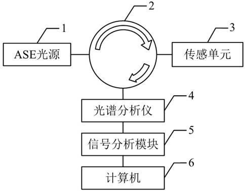
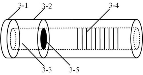
[0025] Such as figure 1As shown, the structure diagram of the optical fiber magnetic field and displacement sensor filled with ferrofluid is provided for the present invention, the ASE light source (1) emits a light beam that is transmitted to the circulator (2), and the output beam of the circulator (2) is transmitted to the sensing unit (3) In the FBG(3-4) side, the light beam is reflected and transmitted at the FBG(3-4), and the transmitted light is transmitted to the Fabry-Perot cavity (3-3), where total reflection occurs, and then passes through the membrane The sheet (3-1) is reflected to the FBG (3-4), and the reflected beam is output to the spectrum analyzer (4) through the circulator (2). When the displacement changes, the sensing uni...


PUM

PropertyMeasurementUnit
lengthaaaaaaaaaa
wavelengthaaaaaaaaaa

Abstract

The invention provides an optical fiber magnetic field and displacement sensor filled with magnetic fluid. The optical fiber magnetic field and displacement sensor comprises an ASE light source (1), a circulator (2), a sensing unit (3), a spectrum analyzer (4), a signal analysis module (5) and a computer (6). According to the invention, a Fabry-Perot cavity and an FBG sensing principle are combined, sensing is carried out by cascading the Fabry-Perot cavity and the FBG, so that a light beam generated by an ASE light source generates an interference spectrum at the FBG, displacement measurement is realized through detection of a reflection spectrum wavelength, and the displacement is measured according to a reflection peak generated by the FBG and the change of a detection magnetic field. And signal processing is performed through the signal analysis module, so that processing on a computer is realized, and the purposes of digitization and intellectualization are achieved. According to the invention, double-parameter detection is realized, the cross sensitivity is small, the sensor size is small, output can be carried out on a computer, and the purpose of simultaneously monitoring the magnetic field and the displacement in real time is realized.

Description

technical field [0001] The invention belongs to the technical field of optical fiber sensing, in particular to an optical fiber magnetic field and displacement sensor filled with magnetic fluid. Background technique [0002] Optical fiber sensor is a new type of sensor, which has the characteristics of high sensitivity, high long-term reliability, high signal-to-noise ratio, and small size. Nowadays, the development speed of fiber optic sensors is extremely rapid, and with the improvement of sensor requirements in petrochemical and aviation fields, common Bragg grating sensors can no longer meet the needs, while fiber optic Fabry-Perot cavity sensors are resistant to harsh environments, etc. Superior features provide effective means for these fields. Therefore, designing a fiber composite structure based on Fabry-Perot cavity and FBG, which can monitor displacement and magnetic field, has the following advantages: small size, long life, low manufacturing cost, high-precisio...

Claims


Application Information

Patent Timeline
Patent Type & Authority Applications(China)
IPC IPC(8): G01R33/032G01B11/02
CPCG01R33/032G01B11/02
Inventor 沈涛袁航王瑞亚
Owner HARBIN UNIV OF SCI & TECH
Learn More