Oil-gas mixed transportation system

A mixed transportation and oil-gas technology, applied in the charging system, turbine/propulsion fuel delivery system, liquid fuel engine, etc., can solve the problems affecting the safe, reliable and efficient operation of centrifugal aviation fuel pumps, and improve the oil-gas mixture. The effect of conveying capacity, reducing the speed of implication, and reducing the rate of cavitation

Pending Publication Date: 2022-04-26
CHENGDU KAITIAN ELECTRONICS
View PDF41 Cites 0 Cited by
  • Summary
  • Abstract
  • Description
  • Claims
  • Application Information

AI Technical Summary

Problems solved by technology

In extreme working conditions, there will be a mixture of RY-3 aviation kerosene liquid, gas and air in the centrifugal aviation fuel pump, which will affect the safe, reliable and efficient operation of the centrifugal aviation fuel pump

Method used


Image

  • Oil-gas mixed transportation system
  • Oil-gas mixed transportation system
  • Oil-gas mixed transportation system

Examples


Embodiment 1

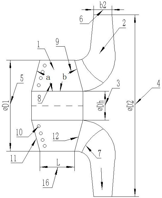
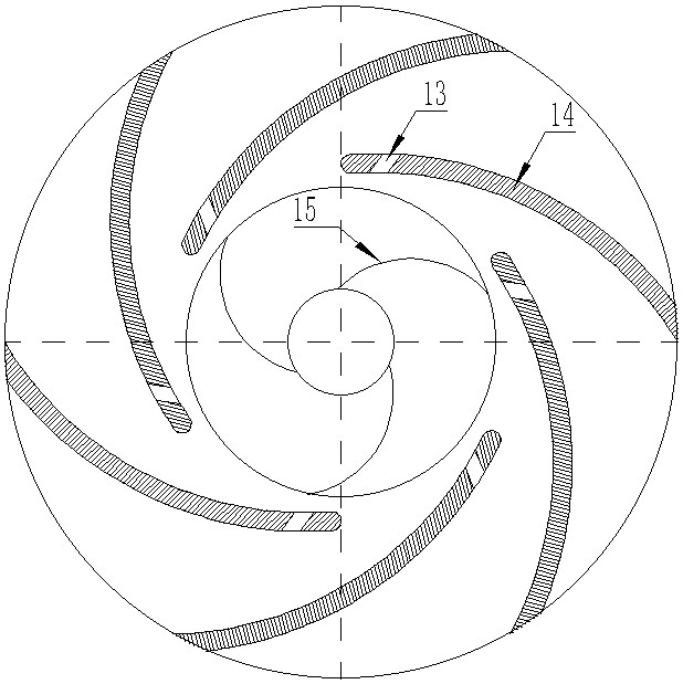
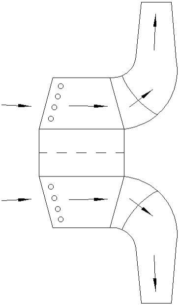
[0026] An oil-vapor mixed transmission system, such as Figure 1-Figure 3 As shown, it includes a pre-supercharged auxiliary impeller 1 and a cylindrical blade main impeller 2 arranged in sequence from front to back, and a spiral axial flow impeller with a variable pitch spiral structure is used as the pre-supercharged auxiliary impeller 1; the cylindrical blade main impeller 2 The head of the front supercharging sub-impeller is provided with a slot jet groove 13; the blade inlet edge 11 head of the pre-supercharging sub-impeller is rounded, and the blade head of the pre-supercharging sub-impeller 1 is provided with several cylindrical blade main impellers. The inlet side 7 of the vane is parallel to the exhaust hole 10; the impeller of the oil-gas mixed transmission system rotates clockwise, and the vapor phase is entrained by the liquid and enters the pre-pressurized auxiliary impeller 1, and enters the cylindrical blade main impeller under the action of lift 2. Enter the pr...

Embodiment 2

[0029] This embodiment is optimized on the basis of embodiment 1, such as figure 1 As shown, the blade inlet side 11 and outlet side 12 of the pre-supercharged auxiliary impeller form an included angle a8 and an included angle b9 with the hub 3 respectively, and the angles of the included angle a8 and the included angle b9 are 60° ~80°, which can ensure small impact on the inlet of the main impeller.

[0030] Further, as figure 1 As shown, the pitch-variable helix of the pre-supercharged auxiliary impeller 1 increases in pitch as the axial length 16 increases, and the wrap angle formed by the blades is 270°-300°. The variable-pitch helix has good cavitation resistance, and the equidistant helix is ​​stronger in confining the fluid. When the blade wrap angle between 300 and 360 is used, the pressure changes drastically. The present invention proposes that the wrap angle of 270° to 300° can Reduce the situation where the pressure on the blade changes drastically when it is in ...

Embodiment 3

[0033] This embodiment is optimized on the basis of Embodiment 2. The inlet diameter and hub diameter of the pre-supercharged auxiliary impeller 1 and the cylindrical blade main impeller 2 are equal, and the blade outlet edge 12 of the pre-supercharged auxiliary impeller There is a gap with the inlet edge of the cylindrical blade main impeller 2 . The same diameter can ensure that there is no pressure drop between the pre-charged auxiliary impeller and the cylindrical blade main impeller, and the flow is smooth; the gap ensures the clearance fit between the two and the uniform flow state at the inlet of the cylindrical blade main impeller.

[0034] Further, as figure 1 As shown, the ratio of the inlet diameter 5 of the pre-supercharged auxiliary impeller to the outer diameter 4 of the cylindrical blade main impeller is less than or equal to 1; the ratio of the outer diameter 4 of the cylindrical blade main impeller to the outlet width 6 is less than or equal to 10. The presen...


PUM


Abstract

The invention discloses an oil-gas mixed transportation system which comprises a front pressurizing auxiliary impeller and a cylindrical blade main impeller which are sequentially arranged from front to back, and the front pressurizing auxiliary impeller is of a variable-pitch spiral structure; a gap jet flow groove is formed in the head of the cylindrical blade main impeller; the head of the blade inlet edge of the front pressurizing auxiliary impeller is rounded, and a plurality of through holes parallel to the blade inlet edge are formed in the blade head of the front pressurizing auxiliary impeller; the operation mode of the impeller of the oil-gas mixed conveying system is clockwise rotation, and a gas phase is wrapped by liquid to enter the front pressurizing auxiliary impeller, enters the cylindrical blade main impeller under the action of lift force and enters the pumping chamber under the action of centrifugal force. The cavitation bubble separation rate of the centrifugal aviation fuel pump during small flow can be effectively reduced, the oil-gas mixed conveying capacity of the fuel pump is improved, the operation stability of the fuel pump under the limiting working condition is improved, and the exhaust capacity of the aviation fuel pump at the starting stage and under the non-design working condition can be improved.

Description

technical field [0001] The invention belongs to the technical field of an oil-vapor mixed delivery impeller, and in particular relates to an oil-gas mixed delivery system. Background technique [0002] The aviation fuel pump is a special aviation mechanical and electrical equipment, which is the core component of the fuel system. The aviation fuel pump is mainly used to transport various aviation fuels, and provides certain flow and pressure for the engine and fuel system. Aviation fuel pumps can be divided into centrifugal type, vortex type, volumetric type and jet type from the vane type; from the drive mode can be divided into: 28V low voltage DC, 270V high voltage DC, 115V AC; from the maintainability can be divided into: integrated type and separate type Installed type; From the function, it can be divided into oil supply pump, starting pump, heat dissipation pump and emergency oil drain pump, etc. [0003] Centrifugal aviation fuel pumps belong to the category of avi...

Claims


Application Information

Patent Timeline
Patent Type & Authority Applications(China)
IPC IPC(8): F04D1/02F04D29/18F04D29/22F04D29/24F04D29/66F02C7/22
CPCF04D1/025F04D29/185F04D29/181F04D29/2255F04D29/2272F04D29/242F04D29/669F02C7/22
Inventor 王维军赵鑫李泰龙何江帆
Owner CHENGDU KAITIAN ELECTRONICS
Why Eureka
Try Eureka