A kind of oil-based drilling fluid regeneration treatment method

A technology of oil-based drilling fluid and treatment method, which is applied in the field of oil-based drilling fluid regeneration treatment, can solve the problems of affecting the performance of the configured drilling fluid, reducing thermal efficiency, and high solid content of recovered oil, and achieves complete and efficient reduction and recycling. Economic benefits, the effect of solving environmental risks

Active Publication Date: 2022-06-17
河北迪运化工科技有限公司
View PDF4 Cites 0 Cited by
  • Summary
  • Abstract
  • Description
  • Claims
  • Application Information

AI Technical Summary

Problems solved by technology

[0003] Among them, the chemical demulsification-separation process uses chemical agents to demulsify the waste drilling fluid, and recovers the liquid phase through mechanical separation. There are common problems such as high solid content in the recovered oil and the impact of chemical residues on the performance of the prepared drilling fluid.
The extraction process is a technology that uses one solvent to extract the solute from a solution composed of another solvent. There are problems such as the residual extractant affecting the performance and toxicity of the recovered oil.
The traditional distillation process adopts one-time feeding and continuous heating and evaporation to recover oil-based drilling fluid. There are problems such as large equipment occupation, low evaporation efficiency, high energy consumption, coking of equipment, affecting production, and reducing thermal efficiency.

Method used


Image

  • A kind of oil-based drilling fluid regeneration treatment method
  • A kind of oil-based drilling fluid regeneration treatment method
  • A kind of oil-based drilling fluid regeneration treatment method

Examples


Embodiment 1

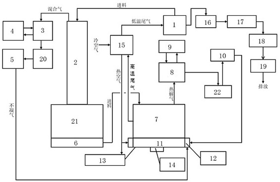
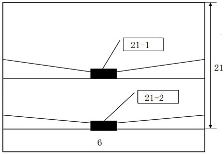
[0044] Take the oil-based drilling fluid from a mud station in Nanhai, CNOOC, with a density of 1.25g / cm³, preheat the oil-based drilling fluid to any temperature of 75℃-90℃ through the drilling fluid preheating tank 1, and transport it to the vacuum low temperature high efficiency membrane type In the evaporator 2, the pressure value of the vacuum low-temperature high-efficiency film evaporator 2 is set to be ≤-0.095MPa, and the set temperature range is 100-300°C. The evaporated gas phase is condensed and collected to obtain the liquid phase, and the liquid phase enters the first A collection tank 20 is recovered, and the oil-solid mixture enters the mixed collection tank 21 .

[0045] The oil and solid mixture are transported to the circulating pyrolysis desorption device 7 through the plunger pump 6, and pyrolyzed at a temperature of 350°C-500°C. The temperature of the circulating liquid in the condensing device is set to 35°C, and the gas phase is collected by the condensin...


PUM


Abstract

The invention discloses a method for regeneration treatment of oil-based drilling fluid, which comprises the following steps: S1. Pump waste oil-based drilling fluid to a vacuum low-temperature high-efficiency film evaporator for rapid evaporation, and the evaporated mixed gas is cooled into a liquid phase and then enters The first collection tank is recovered; S2, the oil and solid mixture in the vacuum low-temperature high-efficiency film evaporator is pumped into the circulating thermal desorption device for pyrolysis, and the pyrolysis gas enters the controllable condenser to generate condensate; S3, the circulating heat The combustion chamber of the hydrolysis device produces high-temperature tail gas, and the high-temperature tail gas exchanges heat with the normal-temperature air through an air-gas indirect heat exchanger to obtain hot air and low-temperature tail gas; S4, the tail gas is discharged up to the standard; S5, the circulating thermal desorption device discharges the solid phase through the high-temperature spiral ; S6, mixing the recovered liquid phase collected by the first collection tank in step S1 and the condensate collected by the second collection tank in step S2 at a ratio of 5:1 to obtain a mixed solution, and recovering oil and recovered water by processing the mixed solution.

Description

technical field [0001] The invention relates to the technical field of oilfield environmental protection, in particular to a method for regenerating an oil-based drilling fluid. Background technique [0002] Oil-based drilling fluids refer to drilling fluids prepared with mineral oil as the continuous phase. Oil-based drilling fluids are widely used in onshore and offshore drilling operations due to their various excellent properties. After the oil-based drilling fluid is reused for many times, the micro-particles (harmful solid phase) in the drilling fluid system are difficult to be mechanically removed, resulting in a decline in performance, and it is difficult to reuse it, eventually forming a waste oil-based drilling fluid. Proportional dilution of oil-based drilling fluid with new white oil temporarily solves the problem of recycling, but it leads to more and more oil-based drilling fluid volume, more and more difficult performance maintenance, increasing storage costs...

Claims


Application Information

Patent Timeline
Patent Type & Authority Patents(China)
IPC IPC(8): C10G7/00C10G7/04
CPCC10G7/00C10G7/04
Inventor 马树奎荣闯张雪梅张占山李斌张贵磊严海源
Owner 河北迪运化工科技有限公司
Why Eureka
Try Eureka